
A set of tools that – for an affordable price and without difficulties – is capable of identifying and verifying the features of BJTs, FETs, thyristors, diodes, etc.
Until a few years ago, it would have been a utopia to have a very small, portable, relatively cheap and universal tool for the automatic identification of almost all the semiconductor components. Today, however, and thanks to the remarkable advancements in technology microcontrollers with high performances and low cost are everywhere: they enable the creation of such tools, that are essential for those dealing with electronics (be it experimenters, students, amateurs, R & D departments that create prototypes of electronic devices, and also professionals, among which repairers and designers).
We would like to show you two of these semiconductor analyzers, that have been manufactured by a British House that is a world leader in this kind of products: that’s Peak Electronic Design Ltd.
The two products are the Atlas DCA55 and the Atlas PRO DCA75.
The DCA55 may be considered as the basic, entry-level version of the tool, while the “PRO” model adds further functions to the ones of the DCA55. Both are capable of identifying the terminals and of verifying that BJTs, Darlingtons, MOSFETs (both of the enhancement and depletion types), JFETs, TRIACs, SCRs, LEDs, bicolor LEDs, diodes, diode arrays are correctly working; as for the DCA75 PRO: in addition to the previous semiconductor types, it is also capable of identifying IGBTs, Zener diodes and many 3-terminal voltage regulators having an output voltage under 8V.
The most interesting feature of the “PRO” version – that also justifies the difference in the prices – is the capability to be connected to the USB port of a computer (on which the Windows XP operating system – or one of the following ones – is running), and of tracking the typical semiconductor curves by means of a software (that is supplied on a USB key). The other difference between the two versions lies in the possibility to update the firmware of the “PRO” model, so to make further functions available, as they are progressively developed by Peak.
Each semiconductor analyzer is enclosed in a small and elegant plastic container, and powered by a small battery (one 12 V GP23A for the DCA55, one AAA for the DCA75) and supplied with 3 small golden spring contacts, to which to connect the terminals of the components to be tested, and that are also available as spare parts sold by Peak (in the case they were damaged during the usage) along with other parts (among which there is the same container).

Let’s see how both models behave during the testing of a bipolar transistor (BJT): once the three terminals of a device are connected, if the latter is damaged, the “Unknown/Faulty component” indication will appear on the LCD display or, in the case of one or more junctions being shortcircuited, the Atlas DC55 will display “Short circuit on Red Green Blue”, depending on the junctions involved, while in the case of a similar malfunction, the DCA75 PRO would display the “Red, Green & Blue leads shorted” indication; if on the other hand the component is not damaged, the DCA55 will return the type (germanium, silicon, darlington, NPN or PNP) and the possible presence of protection diodes, in parallel to the C-E junction. By scrolling what is visualized on the display, via the “scroll/off” button, the pinout and the colour of the clamp to which the terminal is connected are returned. If you keep pressing the scroll button, the hfe current gain, the related test current, the VBE (with the current it is referred to) are displayed, in addition to the leakage current (Icbo).
The “PRO” version has a display that visualizes the information on three lines instead of two, and moreover it also returns the graphical symbol of the component connected for the measuring, which is useful to immediately identify – at a glance – the semiconductor to analyze.
Even in this case, in order to display the various pieces of information that are related to the transistor being tested, it is necessary to scroll the display via the “scroll” button. In both models, the complete component testing requires a few seconds from the pressure of the “on – test” button. Similarly to the BJTs, the analysis of the MOSFETs returns their type (Enhancement or Depletion) with the related symbol (in the case of the “PRO” model), the pinout, the threshold voltage and the current at which the latter is determined.
As regards the JFETs, given that their structure is essentially symmetrical with respect to the gate, the two tools aren’t usually capable of distinguishing the drain from the source and therefore they only identify the GATE terminal; the DCA75 is also capable of identifying the pinch-off voltage (indicated as VGS(off)), the VGS(on) and the related DRAIN currents as well as the transconductance and the IDss.
Another very useful function for both models is the test concerning the LEDs and the double LEDs, that allows to quickly identify the threshold voltage (VF) and the current at which the latter is measured, in addition to the polarity. Moreover, during the analysis the component is briefly lighted up, therefore it is also possible to see their colour (or the colours, in the case of a bi-colour device).
As mentioned before, both the Atlas devices are capable of testing SCRs and TRIACs (with a driving current under 10 mA). Figure shows how both components are identified by the two analyzers.

Figures show the Atlas DCA75 pro that identifies a 7805 regulator, and that highlights the voltage output and the voltage drop between input and output, in addition to the pinout.


Figure shows a collection of screens from the DCA55, that have been acquired during various test types.

The “PRO” model is capable of identifying the Zener diodes having an operating voltage that is not exceeding 11 V; in the case you wished to test devices having a greater voltage (and up to 50 V), we advise you to use the Atlas ZEN50, that is also capable of testing VDRs, TVSs and Transzorbs, with a maximum resolution of 20 mV and test current that may be selected at the values of 2 mA, 5 mA, 10 mA and 15 mA; the Atlas ZEN50 – specifically designed for the Zener diodes – is excellent at measuring the conduction features of many other component types such as normal diodes, LEDs, and transient voltage suppressors such as VDRs, TVSs and TransZorbs. It is capable of measuring the dynamic resistance of the component (by carrying out three reading groups as for the current and the voltage, so to obtain a curve passing through three points in the voltage-power diagram), which is useful in order to identify the rectifying capabilities.

An important difference with respect to the DCA55 and DCA75 PRO models lies in the fact that the ZEN50 has been designed so to polarize the Zener diode in an inverse way, and therefore its two test terminals are identified by the red and black colours and their placing must be respected (red on the Zener diode’s cathode and black on the anode). This remark is particularly important in order to avoid to damage possible LEDs that are connected to the tool, whose testing is considered by the component’s specifications, but if the polarity is not respected, the LED will be irremediably damaged by the high inverse voltage, that may reach 60 V. Even the ZEN50 has the same type of compact plastic container, only the applied identification label and the colour change (green for the ZEN50, blue for the DCA55 and dark grey for the DCA75).
A function that distinguishes the DCA75 from the DCA55 is its capability of tracking the component’s curves, once it is connected to the USB port of a computer that is running a Windows operating system (from XP and on), thanks to the provided software.

As indicated by the instruction manual, the tool must not be connected to the PC until the end of the program installation.
Once it is installed, it is quite intuitive to use the software: once the component to be tested is connected, you will have to click on “TEST”. On the basis of the semiconductor’s type, you will have to select (from the “Graph” drop-down menu) the quantities you are interested in and that you want to be displayed.
Figure shows the typical IC-VCE curves, that have been tracked for a TIP35C power transistor, after having changed the default value for the “points” from 51 to 100 and the one for the “traces” from 5 to 10.
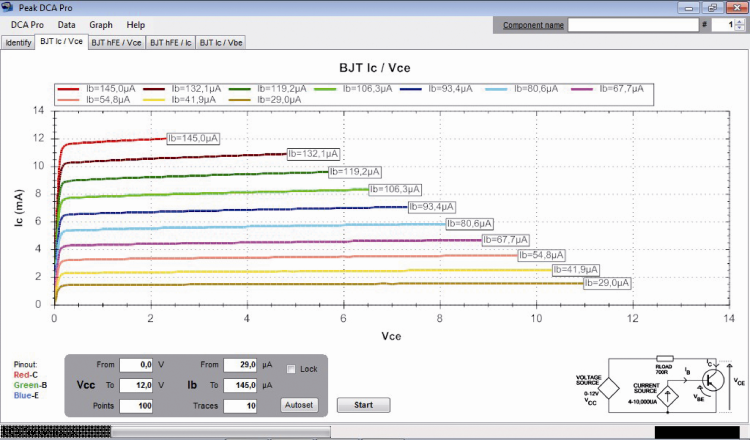
Figure shows a very useful program feature: the possibility to track the curves in a comparative manner, so to display the curves related to two or more components in the same diagram.

In addition to the graphical representation of the curves, it is also possible to export the data in a numerical form on a spreadsheet, by using the “Data” menu.
Even though the usage of these tools is really an intuitive and immediate one, in order to take advantage of all the possibilities offered, and to make a proper use of them, we advise you to carefully read the instruction manual that is supplied, and that is available – in PDF format – at the manufacturer’s website, both in English and in Italian (with the exception of the PRO model, whose instructions are available in English only, as for the digital format) at the following webpage.
Conclusions
In the years we had the chance to evaluate and propose various semiconductor analyzers, but none of them was really a complete one, and capable of testing such a wide range of components, as the analyzers by Peak do. The quality of the said tools, that we verified during the lab tests, makes us advise them.
These tools – that have a small size but a really interesting price – are recommended for all those dealing with electronics, be it as a hobby or for professional purposes; once you start to use them, in no time they will become an essential help in your lab.
Try them out: you will not but agree with us, on their quality and usefulness!
From openstore
