Let’s create an electrically controlled lock that is opened by means of an always different code that is generated by our smartphone, on the basis of an algorithm that takes the time into account.
If you are a customer of an online bank, you will probably be using a device named “token” already, in order to access the home-banking services, or to authorize the operations. These devices, that are often akin to a key ring, are provided with a display on which – every X seconds or when a button is pressed – a numeric code appears: it is always a different one and is named OTP (one-time password); the code is similar to the rolling-code of a high security remote control and is generated by means of a pseudo-casual algorithm that also takes the timestamp into account, that is to say, the current time. Recently, even the soft-tokens have started to spread, that is to say, applications for smartphones that generate the same codes without need to have an additional physical device with you.
The project presented in this article will allow you to create a lock that may be opened by typing – by means of an alphanumeric keypad – a code generated by an application found on your smartphone. As we will see later, it will be possible – by means of simple modifications to Arduino’s sketch – to link the lock to one or more mobile phones and to modify its behaviour.
THE OTP CODE
The generation of OTP codes starts from the initial data to which an algorithm is applied, that is to say, a series of mathematic operations that tranform the said data into a numeric code. The algorithm is of the deterministic kind: starting from the same initial data, you will always obtain the same code. To generate a different code, we therefore need that at least one of the pieces of data is a variable; for this purpose, the most widespread tokens use the number of clicks on the button as a variable (therefore, a new code is generated each time the button is pressed) or a value that is tied to the actual time and date.
Generally, there is no direct communication between those who generate the codes (in our case, the application on the smartphone) and he who validates them (the lock): the verification of the typed code is carried out thanks to the fact that both share the same starting data and the same algorithm and therefore they may generate the same code at any given moment .
There are various algorithms for the generation of the codes and moreover some manufacturers use some closed systems, thus making their tokens compatible with “certified” applications only. For our project, we decided to choose an open algorithm, defined by the RFC6238 – “TOTP: Time-Based One-Time Password Algorithm” specifications (https://tools.ietf.org/html/rfc6238); in this way it will be possible to generate the codes from whatever application or physical token that is compatible with such specifications.
The algorithm is based on a secret key (shared secret) and on the value of the timestamp Unix, that is to say the number of seconds elapsed from the Epoch date, that corresponds to the midnight of a certain day, 01/01/1970. It is very important – we will see that again later – that such a timestamp is expressed accordingly to the UTC time zone and that the smartphone and the lock are synchronized as regards the time. While by now all the mobile phones are automatically synchronized via the Internet, for our lock it will be essential to have a “clock” available; it must be as accurate as possible, and in this specific case we will achieve this purpose by means of a RTC module.
SKETCH
In order to generate codes that change every n seconds, the timestamp is divided by the desired duration – expressed in seconds – and only the quotient of the division is taken into consideration: such a number will be a constant for the whole duration of the interval. In Table 1 we may see some examples, so to better undestand the mechanism.

The Hardware
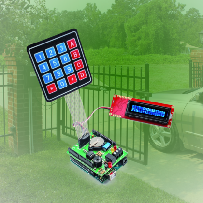
The lock that we will create will be based on an Arduino board, to which we will apply a shield to which we will connect:
- an alphanumeric membrane keypad for typing in the codes;
- a serial display so to display the state of the lock and of the codes that have been typed;
- a relay for the activation of an external load (as an example, an electrolock) if the code that has been typed is correct;
- a buzzer, so to generate sound warnings;
- two LEDs (a red and a green one) so to display the lock’s state;
- a RTC (real-time clock), so to have a timestamp value that is always updated and exact;
- a buffer battery, so to power the RTC, even if the board is not powered.
In order to make it easier to achieve the project, we prepared a shield that includes all the above listed components, and whose circuit diagram is illustrated in these pages. The Real Time Clock is a DS1307 integrated circuit by Maxim/Dallas that uses a 32.768 kHz crystal (Q1), that supplies the base frequency for the internal oscillator; the integrated circuit is a BCD counter that counts seconds, minutes, hours, days, months and years, and that is supplied with 56 byte of non-volatile static RAM; the component automatically determines which ones are the months having less than 30 days, and carries out the correction concerning the leap year.
The clock may operate in the 12h or 24h mode, with the indication of the hours before midday (AM) and of the ones after midday (PM). The information concerning the time and date is located in a dedicated register and transferred to the outside, to Arduino’s microcontroller by means of the l’I²C-bus (of which the chip is supplied); Arduino acts as a master unit of the I²C-Bus, while the Maxim-Dallas’s chip is the slave.
In addition to this, the DS1307 has a programmable clock output: more exactly, it makes a square wave acquired from the RTC’s clock frequency (that is in turn determined by the 32.768 kHz crystal, that is connected to pins 1 and 2) that, by means of a dedicated internal divider, may have its frequency divided, thus obtaining 1 Hz, 4.096 kHz, 8.192 kHz or the whole clock frequency.

The frequencies that may be obtained have not been randomly selected: for example, 1 Hz may be useful in order to make the two points or the point of the seconds flash, in a possible display showing the time, in a stand-alone clock application. The condition of the output of an auxiliary clock (SQWE, pin 7) is defined by opportunely setting the logic state of the RS0 (0) and RS1 (1) bits of the control register, accordingly to what has been shown in the specific box: for example, 1 Hz is obtained with both bits set to zero. Please notice that when both the fourth (SQWE) and the seventh (OUT) bits are found at logic zero, the clock output is fixedly set at a low level; if – on the other hand – the bit 7 is at logic 1 and the bit 4 at zero, the output constantly takes the high state. In our shield, the SQW output drives a LED in sink mode, by making it pulse at the same frequency of the generated square wave; moreover, by means of the JSQW bridge it is possible to decide if to have Arduino read (or not) the corresponding signal, by means of the A3 line.
As hinted before, this auxiliary clock may be useful in order to activate some display or to start certain sequences: for example, in order to play a buzzer every second, the whole of this without engaging Arduino in timing routines.
The DS1307 also has a control circuit that is capable of verifying the absence or insufficiency of the main power (Vcc) and make sure that the voltage needed for its functioning is drawn from the backup battery, that in our case is a 3 V CR2032 button cell, that ensures an autonomy of about 6 months when the power is missing and that has to be connected between the pin 3 (Vbat) and ground (pin 4, that is to say, GND). The power control section is sized so that it may carry out two tasks: to preserve the memory on which the data concerning the time and date is stored, and to keep the clock counter active. The first one is carried out by storing the corresponding information in the non-volatile RAM, while the second one is carried out by the backup power, drawn from the battery or from the buffer battery connected between pin 3 and 4. The power control section intervenes on the other DS1307’s functions, by blocking the communication with the I²C-bus and the generation of a possible SQW auxiliary clock, so to minimize the energy consumption and to extend the autonomy as much as possible. The protection happens when the voltage read between the main power’s pin (8) and ground (4) is less than 1.25 times the battery voltage.
The RTC module, that must be powered with a well stabilized 5 V direct voltage, draws a current (really a minimal one) of approximately 1.5 milliampere, that goes down to 500 nA when it is the battery to power it. The 5 V are drawn from the Arduino line having the same name (5 V).
In order to know time and date, Arduino has to query the DS1307 by means of the I²C-bus (of which the chip is supplied); at each query, the DS1307 replies by sending the answer and the information concerning date and time to the ATmega (still through its I²C bus). In our shield, the RTC is therefore connected to the two Arduino’s pins, SDA and SCL; the two 1 kohm resistors, R2 and R3, act as pull-up resistors for the I²C bus, that is needed by the Arduino’s ATmega microcontroller for the query of the DS1307, for the purpose of polling the time and reading it.
The relay is commanded by Arduino’s pin 13 via the T1 transistor; while the D1 diode is needed in order to suppress the inverse voltage that the relay’s coil generates when the transistor enters the interdiction state.
The LD4 LED, connected in series with its resistor, and in turn in parallel with the relay’s coil, is turned on when RL1 is active. Two additional LEDS, a red and a yellow one, are connected to the Arduino pins 11 (LD3) and 12 (LD2), by means of two current limiting resistors. The buzzer is driven by Arduino’s pin 6.
Finally, on the shield two strip connectors are found: a 8-pin one, to which to connect the membrane keypad, and a 3-pin one, to which to connect the serial interface LDC display. On the other hand, the tripolar terminal blocks allow to connect an external load to the relay: the central contact of the terminal blocks is the one that is normally closed (NC), while the side ones are the normally open contact (NO) and the common one (C).

THE SKETCH
The sketch to be installed on Arduino may be downloaded from the project page. As for its compiling, it is needed to install three libraries:
- keypad;
- RTClib;
- TOTP Library.
All the libraries may be installed by means of the Library Manager that is included in the most recent versions of Arduino IDE; from the Sketch menu we will give the Include Library –> Manage Libraries command. Let’s type in the name of the library in the search field and, once it has been found, let’s click on the Install button, as shown in figure.

Now, let’s analyze the sketch, starting from the interfacing towards the external peripherals. Thanks to the shield, the alphanumeric keypad is automatically connected to eight digital Arduino pins (2-3-4-5 for the lines, 7-8-9-10 for the columns).
The Listing 1 shows how the Keypad library is used in order to correctly read the buttons that are pressed: as a first thing the size of the keyboard (4 rows x 4 columns) is defined; afterwards its layout (the various keys and their position) is configured, and finally the Arduino pins to which it is connected. Once the correct configuration has been set, it is possible – when inside the sketch – to read the key that has been pressed via the keypad.getKey() instruction: such an instruction returns a variable of the char kind that contains the symbol of the key pressed, and the NO_KEY constant, if no button has been pressed.
Listing1
// configurazione della tastiera
#define KEY_ROWS 4
#define KEY_COLUMNS 4
char keys[KEY_ROWS][KEY_COLUMNS] = {
{‘1’,’2’,’3’,’A’},
{‘4’,’5’,’6’,’B’},
{‘7’,’8’,’9’,’C’},
{‘*’,’0’,’#’,’D’}
};
byte rowPins[KEY_ROWS] = {5, 4, 3, 2};
byte colPins[KEY_COLUMNS] = {10, 9, 8, 7};
Keypad keypad = Keypad(makeKeymap(keys), rowPins, colPins, KEY_ROWS, KEY_COLUMNS);
The LCD display that has been chosen for the project is of the serial kind, that is to say it is possible to control it via a single Arduino digital pin, by sending some simple instructions. In order to not engage Arduino hardware serial (that is used, as we will see later, in order to configure the RTC), a software serial has been defined inside of the sketch, it uses the A2 pin as data transmission pin (TX) towards the display. By sending a character via serial to the display, it shows it in the pointer’s current position, moving then the latter by a character to the right or in the row below, if the end of the line was reached. The 254 (0xFE) character is the exception, it allows to send a command and the 124 (0x7C) character to the display, the second one allows to regulate the intensity of the retroillumination. In the data-sheet you may find the list with all the available commands for the display control; in the sketch the commands are used in order to move the pointer to the beginning of the first line (command 128) and to the beginning of the second line (command 192), as shown in Listing 2.
Listing 2
void pulisciSchermo() {
displaySerial.write(254);
displaySerial.write(128);
displaySerial.write(“ “);
displaySerial.write(“ “);
}
void aggiornaSecondaRiga() {
displaySerial.write(254);
displaySerial.write(192);
displaySerial.write(“PIN --> “);
displaySerial.write(254);
displaySerial.write(200);
for(int i = 0; i <= codiceIndex; i++)
displaySerial.write(codiceInserito[i]);
}
The buzzer that has been chosen is not of the active kind, therefore in order to release an acoustic note, we have to power it with a variable unidirectional voltage (or an alternating one as well) to the frequency of the desired note; in our case Arduino’s tone(pin, frequency) function comes in handy, it allows to generate a square wave of the specified frequency on the indicated pin. In our case, the instruction that has been used is tone(PIN_BUZZER, 440); that makes Arduino generate a square wave at the frequency of 440 Hz, for the purpose of making the buzzer giving off an acoustic note corresponding to the “International A”, that is to say the diapason’s frequency (LA4). The pin is named as in the definition of Arduino’s initialization of the I/Os, inside of the setup.
Let’s see now the most important part of the sketch: inside of the loop() it is continuously verified if a new character has been received via serial or if a button has been pressed on the keypad. In the first case, the character is added to a buffer and, if it is the NEWLINE (0x0A) character, it moves on to understand the command received. In the second case, the new figure that has been typed is added to a buffer and, if the 6 digits code is completed, the said code is verified. Two peculiars cases may occur: when pressing the * button the last figure typed is deleted, while when pressing the # button the whole code typed until now is deleted.
The code lines concerning the verification of the code that has been typed in via keyboard is the one you may find in Listing 3; let’s comment it briefly: as a first thing the current timestamp value is read from the RTC. After that, it is divided by 30, that corresponds to the validity interval of each code. Afterwards, thanks to the totp.getCodeFromSteps() function, 3 OTP codes are generated, they are related to the current interval, to the previous one and to the following one; the usage of three codes allows in fact a small misalignment between the time found in the RTC and the one of the mobile phone. The three codes are therefore compared to the one typed in via keyboard, and if one corresponds, the lock is opened.
Listing3
DateTime now = rtc.now();
long GMT = now.unixtime();
long timeStep = GMT / 30;
bool codiceOk = false;
for(int i = -1; i <= 1; i++) {
har* codiceGenerato = totp.getCodeFromSteps(timeStep + i);
if(strcmp(codiceInserito, codiceGenerato) == 0) codiceOk = true;
}
STARTING SETUP
In order to use the lock, as a first thing it is needed to install an application on your smartphone, it must be capable of generating OTP codes with the chosen algorithm.
As regards iOS and Android, it is possible to install the Google Authenticator application from the corresponding market, while as for Windows Phone it is possible to use Authenticator+. All the applications are free; the web addresses are as follows:
- Google Authenticator for iOS: https://itunes.apple.com/it/app/google-authenticator/id388497605?mt=8;
- Google Authenticator for Android: https://play.google.com/store/apps/details?id=com.google.android.apps.authenticator2&hl=it;
- Authenticator+ for Windows Phone: https://www.microsoft.com/en-us/store/apps/authenticator/9nblggh08h54.
As explained in the beginning of the article, it is needed that the application and the sketch on Arduino share the same private key, in order to generate the same codes; in order to simplify the configuration we prepared a web application at the following address: http://www.lucadentella.it/OTP/.
After having typed in a password composed of ten characters of your choosing, press the GO button: the array to be inserted in Arduino and the code or the QR Code for the configuration of the app will appear. It is also possible to change the name of the account that will be displayed by the app, below the generated codes.

The field value of the Arduino HEX array must be reported in the CONFIG.h file of the sketch .

While in order to configure the app it will be possible – from the menu for the addition of a new account – to decide to manually insert the code or to read the QR Code by means of the mobile phone’s camera for the automatic configuration.

In both cases, once the configuration has been completed, the application will start to generate the codes.

We finally have to verify the time found on the RTC, remembering that it must be synchronized with the one of the smartphone as much as possible, and accordingly to the UTC time zone (on the other hand it is not needed that the smartphone is set to the said time zone, since it is the application itself to carry out the correct conversion with respect to the local time). The sketch allows to configure the RTC by means of serial commands: let’s open the Serial Monitor and configure it for 9.600 baud via Newline as line ending.

If we sent the ? character, the sketch will display the current time.

If the said time is not correct, it is possible to update it by sending the !ggMMaahhmmss command. As an example, in order to configure the day as 01/02/2016 at 10:30:20, the command to be sent will be !010216103020. If the command is correct, Arduino will reply with the confirmation of the configuration and will display the new time.

LOCK CONFIGURATION
The sketch that has been written for the project allows for some customizations, that may be carried out by modifying the CONFIG.h file. As a first thing, it is possible to modify the behaviour of the lock, by choosing one of two different modes that are alternative to each other:
- PULSE_MODE = the lock remains open for a certain amount of milliseconds and then it is automatically closed;
- STABLE_MODE = the lock remains open until a button is pressed.

If the PULSE mode has been chosen, it is possible to change the OPENING_TIME constant, so to define the time (please specify the number of milliseconds) during which the lock will remain open, as a consequence of each activation of the relay. If on the other hand the STABLE mode has been chosen, it is possible to change the CLOSING_KEY constant, so to choose which key will be used in order to close the lock (it is very important that the chosen key is always indicated between quitation marks!).
Finally, it is possible to deactivate the sound of the buzzer, by commenting the #define BUZZER_ON line.
This being said, we will end by remembering that the relay that has been mounted on the shield allows to manage users that draw up to 1 ampere in circuits operating at a maximum of 60 Vcc: therefore the electrolocks, that typically operate at 12/24 Vcc or ca, are fine. If you think about managing loads having a greater power you will have to use a servo relay whose coil will be powered by means of the C/NO changeover of the relay placed over the shield, that you will therefore use as a switch. The galvanic isolation will be ensured by the servo relay.
From Openstore

Hi,
You refer to the sketch being available for download from the project page. I have searched and cannot find the link. Could you please advise where it is, and if it is in English
Thanks
Jim
https://www.futurashop.it/image/catalog/data/Download/FuturaOTP.zip
It is not in English. All the links are in the store https://store.open-electronics.org/index.php?route=product/product&product_id=943&search=ft1234
PS
i think the project is terriffic
Jim
Please do NOT wire the keypad to the device! Have the keypad electrically isolated, with optical cables, and power it with a solar cell. Otherwise anybody can fry the locking mechanism, so you yourself will have trouble getting in.
And “on the smartphone” raises ALL my hairs! ^^
Use a small separate microcontroller with a flash memory chip, powered solely by shaking it or by body heat, or even by induction from the lock surface. :)