
In order to “visually” highlight the behavior of Arduino programs you must connect a device to the I/O pins, which gives you tangible signals. Normally, if you want to check if a program changes a level of an output pin, answering a command or executing a check routine, or event, you must check it by measuring the voltage level on the pin with a voltmeter. But if we connect this pin to a LED with the correct driver circuit, we can check the behavior of the program thanks to a switch in the LED state: it could be on, off, or partially on, if you connect it to an analog output pin. In a similar way, if the output pin is connected to a relay, we can drive external loads with ease. The same applies to the digital or analog input pins, and analog outputs.
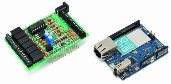
To give a more professional appearance to our projects and to further ensure the reliability of the connections we prepared a experimentation shield in “Arduino” style, indicated mostly for Arduino YUN (but that can also be used with earlier versions).
To give maximum flexibility to the use of the shield, all external connections are mounted on screw terminals. The shield provides six digital outputs connected to as many LEDs to display the status plus relays to activate external loads. You can connect LED strips, cooling fans, buzzers or whatever you prefer. There are also six analog and six digital multifunction inputs three of which can be used as PWM or DAC analog outputs if you prefer (pin 3, 5 and 6.)
The board requires a separate power supply of 12 volts if it is used with Arduino YUN, or it can get power directly from Arduino UNO.
Circuit Diagram

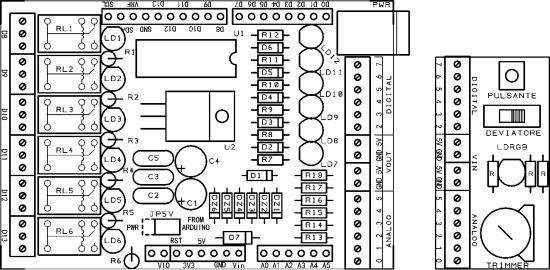
As you can see in the circuit diagram the shield is divided into sections. Each section is specialized in bringing outside the possibility to connect to a specific type of I / O pin. Within each section of the circuit diagram is repeated identically for each of the pins.

Let’s start from the section that serves the digital output pins, which correspond to Arduino pin 8, 9, 10, 11, 12 and 13.
In this section each pin drives a transistor driver circuit coupled to a relay. On the screw terminals all the terminals of the relay are available, the central terminal C, the “normally closed” NC terminal and the “normally open” NO one. The arrangement of the ends on the terminals is visible in the ” Mounting Plan”.
The section that serves the digital input pin affects the Arduino pin 2, 3, 4, 5, 6 and 7, also in this case the description of a module of circuit applies to everyone else. Take the pin 2. When at rest, the pull-up resistance keeps the input level high: it is connected to the positive supply voltage through the LED, which in this state remains off. The protection diode serves to protect the input in the case voltages above 5V are applied, so as not to damage the digital inputs of the Arduino. Pins 2, 4 and 7 can only be used as digital inputs. When the terminal is brought to a low logic level, for example by connecting it to ground with a button, the circuit is closed to ground and the LED lights up. The operation of the LED follows the so-called inverted logic: is on when the pin takes the 0 value (low logic level), and is off when pin assumes a value of 1, a high logic level.
The same applies to pins 3, 5 and 6 when they are configured in the Arduino sketch as digital input pins. These same pin can also be used as an analog output pin. In this configuration it can be driven with values between 0 and 255, so as to provide an output voltage that is proportional to the value set. In this case, since the LEDs are connected to the positive voltage, the voltage applied to the same will be equal to 5V minus the voltage present on the pin. With output set to 0V (set 0 value), the LED will be fully illuminated. The brightness decreases in line with the voltage on the pin until it turns off completely when the PWM value is set to 255 (5V). On the output terminal of each pin, instead, the voltage follows the classic logic, growing in proportion to the PWM value set. All digital inputs have a common ground, which corresponds to the contact “-” on the terminal, in addition, next to the digital input terminal is a terminal with +5 V and GND outputs.
Finally, the section that serves the analogue lines corresponding to pins A0 to A6. Each module presents a series resistor and a Zener diode in parallel. The diode limits the input voltage in case it’s greater than 5.1 volts and the resistance limits the current flowing in the Zener diode in case of intervention.
The shield requires an external power supply with a voltage being between 9 and 12V, separate from the Arduino Yun board as the board cannot provide the current needed to power the shield. The power of the shield is guaranteed from the LM7805 integrated circuit which also sports a protection and stabilization circuit.
JP5V jumper must be placed between the center pin and the PWR connector. In this way it is ensured that the shield and the Arduino Yun are each powered by their own power supply. This shield is designed to operate also with classic Arduino boards and is able to feed them by placing the jumper on the pin “From Arduino”. In the case of Arduino Yun, due to the absorption of current of the board, and in particular of the WiFi module, the power feed of the shield is not able to give a current that is sufficient to power both.

BOM
R1÷R6: 1 kohm
R7÷R12: 470 ohm
R13÷R18: 4,7 kohm
C1: 100 μF 25 VL
C2, C3, C5: 100 nF
C4: 100 μF 25 VL
D1÷D6: 1N4148
D7: 1N5819
DZ1÷DZ6: Zener 5,1V 400 mW
LD1÷LD6: Led 3 mm red
LD7÷LD12: Led 3 mm green
RL1÷RL6: Relay 5V
U1: ULN2003
U2: 7805
Gerber files
In the Store
You can buy this shield from our store

and the production files for the boards are…. ?
I add the gerber files ;-)
http://www.open-electronics.org/wp-content/uploads/2014/02/P1098.zip
Very Good this Shild! Congratulations
How could I open the extension .gbr of Gerber files???
In wait, Thanks,
Edgar
Look in google for gerber viewer
For a Quad band GSM GPRS project, we would like to use GPS, Camera and few analog and digital inputs. Can U Please suggest hardware configuration for a near REAL TIME Video and Telemetry from Vehicles?
You have to use a UMTS module. We haven’t …
yet
How much current does the output relays handle (and the board)?
No more than 1A
Hi can this sheild be used with arduino as grbl