
It can be controlled through logic levels to set the speed and the direction of the rotation of CC brushed motors and stepper motors; outputs have LEDs indicating the rotation direction.
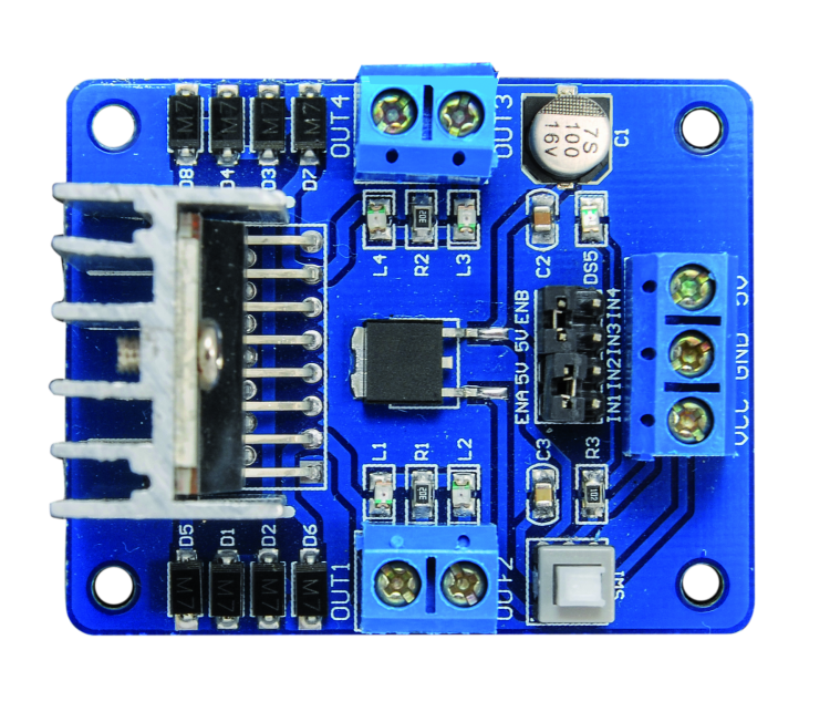
The circuit board we are presenting this time is based on the dual-bridge driver L298N, in a traditionally mounted version in a Multiwatt container with 15 staggered pins; it has two terminal blocks for attaching to DC motors or the coils of a bipolar stepper motor and a terminal block for powering logics and motors. Each of the two output channels of the circuit can provide a maximum current of 2 A, which is enough to drive two 2 A direct current motors or a bipolar stepper motor absorbing 2 A per phase.
Circuit diagram
Now that you have an idea of the circuit performances, let’s get down to it by analyzing the circuit diagram, which is based on the L298N driver by ST: it is a dual H-bridge BJT driver which can be entirely controlled through the EN (enable) and IN (direction) control pins. Each section of this component is made of an NPN bipolar transistor bridge and each bridge is made of two halves in which the BJTs are connected following an almost complementary symmetry, that is the positive-connected transistor is connected to the collector and the bottom one is connected to ground via the emitter (the bridge structure can be seen in picture); therefore, the output is found between the emitter of the positive-connected transistor and the output of the ground-connected transistor.

The transistors bases of each half-bridge are individually piloted by the logic signals coming from the AND ports that have a common input and two separate inputs and are connected to the IC’s IN inputs; the common input is the EN and it activates the bridge so that it can receive the logic signals coming from the INs settings. This configuration allows us to both make use of the IC to pilot four brushed motors in one direction, and then use each half bridge separately, and to use one combined full bridge (by providing the IN control inputs with opposite logic levels) in order to control the rotation of one motor in one direction and the opposite.

In order to better understand the functioning of each single bridge, let’s take a look at the first one, which has 2-pin and 3-pin as outputs (OUT1 e OUT2) and let’s start from the condition in which the respective EN pin (ENA, that is the 6-pin), is at logic zero: in this case the bases of both sides of the bridge are at logical low and transistors are all in interdiction; outputs are in high impedance, this means that they do not conduct in either direction and do not supply current. Now we apply a logical high to the ENA, by applying a voltage of at least 5 V, the outputs of the four ANDs and the respective bridge now will enter into a condition which will depend on the control inputs IN1 (5-pin) and IN2 (7-pin); by applying a high logic level to both of them, the respective half bridge will show a logical high on its output. For instance, if we put 5-pin to logic 1, the positive-connected transistor will conduct and will determine a high voltage level on its output (OUT1), while the ground-connected transistor will be interdicted (because the AND controlling it has its input connected to negated IN1). Under this condition, if we leave IN2 to logical zero, its half bridge will stay with the interdicted upper transistor and the lower one in conduction, while if we also put IN2 to logical high, the OUT2 output will to go to logical high, that means the top transistor will be in conduction and the bottom transistor will be interdicted.

If we invert things, and we leave IN1 to zero and put IN2 to the logical one, OUT1 will show a logical low and OUT2 will go to logical one.
Given the above, we can see that the control of bridge 1 follows Table 1; same goes for the second bridge, so there is no need to repeat it. Moreover, we can see that in order to control a brushed motor and invert its rotation direction we have to connect its terminals between OUT1 and OUT2, then we how to apply, for each direction, a couple of logic levels which are in opposition to the control inputs IN1 and IN2; on the other hand, if we want to control a motor in just one direction, all we need is half a bridge and we are going to apply logical high to the corresponding control input (in this case the motor will be connected between OUT1 or 2 and the ground). By taking a look at this functioning, we can understand that if we are to control a brushed motor that is connected to the outputs of one of the bridges, we can do that by making it spin in one direction or the other one by simply applying opposite voltages at the control inputs, while in order to stop it, we simply have to put said inputs to logic zero: in this case the bridges outputs short-circuit the motor’s terminals with ground, canceling the voltage that the motor itself would tend to produce by spinning idly, therefore charging and applying a slowing action.
Table1

Now that we have explained it how the L298N works, we can see how it’s been employed in our circuit: the IC works in its classic configuration, with a 5 V power source between the 9-pin (logics positive) and 8-pin (power ground and logics ground); the positive side of the power section’s power source (the couple of H-bridges) is Vs and it is connected to the same power source of the motors and the respective protection diodes, labeled Vcc in the circuit diagram. Note that, while voltage is taken directly from the power source terminal block (filtered by C3 capacitor), the logics’ (LVS) can be applied and removed according to the position of the switch of the double deviator SW1; this one allows us to completely turn off the L298N while still leaving voltage on the transistors’ bridges, which however do not absorb current and remain inactive. Having the possibility to deactivate the entire IC by removing the power source allows us to keep the motors power source always connected (power) by operating on a small current such as the one powering the LVS pin. Logics needs are taken care of by the U2 integrated regulator, an SMD 7805 in classic configuration, that is with the input between Vin and GND and the output between Vout and GND; voltage of the latter is well filtered by C1 (minimizing the possible ripple effect due to DC/AC power) and C2 (it filters out voltage impulses due to absorption peaks by the motors), reaches the switch of one section of the double deviator. When this is moved on the lower end (6) the other section is closed between 1 and 2, so that the Vcc input line powers the U2 regulator’s input and Vout powers line 5V with 5 V; on the other hand, when the cursors is on the 4-contact, the other section is closed between 2 and 3, in this case the regulator is not powered and at the same time connection between Vout and 5 V line is interrupted.


Note that, in order to cut the power to the L298N logics we could have simply used a switch connected in series to Vin, but the deviator allows to exclude U2 and to power the circuit with two voltages: Vcc for the motors and 5 V for the logics. This lets us to remotely control the controller from a logic output, for instance through the I/O over the microcontroller and a BC547 transistor.
The 5V line also powers the jumpers with which we can set the enable lines of the two stages (ENA and ENB). The DS5 LED is connected in parallel to the power unit, and it is powered through the R3 resistance which limits its direct current.

The bridges outputs are each connected to two terminal blocks and each has a couple of LEDs connected in anti-parallel, which current is limited by a resistor (R1 for L1 and L2 and R2 for L3 and L4); as a result, for each output, when the red LED lights on, the output provides voltage with a certain polarity and when it lights on in green it means the polarity is inverted; more exactly, for the first bridge, when OUT2 is positive the diodes light is green, while red corresponds to a positive OUT1 output compared to OUT2. As for the second bridge, the green LED lights on when OUT4 output is positive compared to OUT3 while it lights on in red in the opposite situation. Both outputs have Schottky protection diodes (SMD-diodes M7), protecting them from inverse extra voltages produced by the coils of the motor, one connected to the positive and one to the power negative and placed in such a way that they are in interdiction when functioning normally; diodes conduct only if outputs returns inverse voltage impulses due to the effect of the inductive load which is the electrical motor, and this typically happens when power is cut off or polarity is inverted, that is if we put the enable to logics zero (in which case transistors do not conduct current and isolate the motor, as a consequence there are extra voltages that would discharge on the transistors and damage them if it wasn’t for the diodes). As for the L298N control, we brought IN1, IN2, IN3 and IN4 lines outside through a 4-poles, 2.54-step pin-strip. We remind you that in order to realize an on/off or forward/backward control all you have to do is handle those inputs as shown in Table 1, putting ENA and ENB enables to 5 V (you just have to close the relative jumpers), while if we want to manage not only direction but also speed, we must drive the ENA and ENB inputs with PWM signals. By applying a PWM signal to the enables, we can turn on and off the bridge at the frequency of the rectangular wave of control and for the periods set by the duty cycle of the same PWM; this allows us to regulate mean voltage applied to motors and then to regulate the rotational regimen, maintaining and elevated torque even with low rpm.
That’s get back to the directional control now, which is operated through IN1 and 2 and IN3 and 4: as you can see, if we want to control a breach in this configuration, the logic state of IN1 must be opposite to that of IN2 and IN3 must have an opposite state compared to IN4. Motors must be connected to terminal blocks OUT1-OUT2 and OUT3-OUT4.

Whatever application you are going to use this circuit for, remember that the 2 A indicated as maximum current supplied for each output represents the current limit in the motor, even if the required type needs more than one output; in fact, in the case of the stepper motor the outputs are used in couples, one couple for a coil and one couple for the other one, so since current goes out from one OUT and enters from the other, the 2A limit remains valid. Same goes if we control the brushed motors with velocity control and rotational direction; if we connect four distinct motors there will be no problem because each output will provide 2A max.
You are going to need these notes for the power supply specifics: in fact in the first two cases the IC can absorb (on the bridge side and therefore the outputs side) a maximum of 4 A, while in the second case it will need 2A for each connected motor, therefore four motors with absorb up to 8 A. Re the power: remember that you only have to supply power to the motors, which voltage must not exceed 30 Vcc. For what concerns control inputs (IN1, IN2, IN3, IN4) consider that logic 1 corresponds to a voltage of 4,5÷5,5V and zero corresponds to a voltage of 0÷0,7 V.
From openstore
Motor Driver 2A Dual H-Bridge L298

[…] Boris Landoni writes about a new open source project a DC motor controller with control LEDs: […]
Guys, for the next spin I would recommend strongly series resistors on inputs.
A few Kohms gives a large protection against ESD and EOS events coming in on the driving wires for not much money. Overvoltages on the inputs as well as static discharges.
If you use a SMT multipack resistor soldering is easy too, as you are already doing SMT.
I am thinking pins
6, 11, 5, 7, 10 and 12 (ENA, ENB, IN1, IN2, IN3, IN4).
If you really want to go the distance drive the H-bridge through a socketed 74 series DIP buffer IC and again add series resistances on the buffer IC inputs. That way if you get a EOS it kills the throwaway 74 series, not the H-Bridge.
Best, and good work,
Matthew