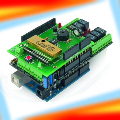
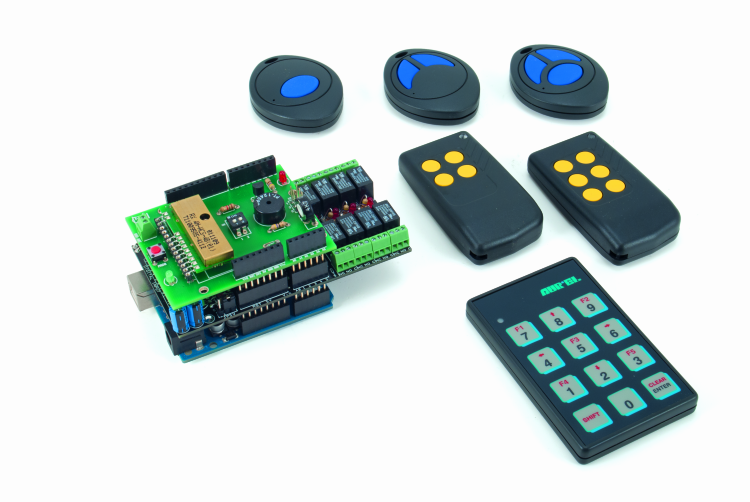
Geared with a shield containing an HCS Microchip encoder/receiver module and an I/O Expander I²C-Bus board, it enables the creation of Arduino based remote controls with 8 channels, expandable to 12.
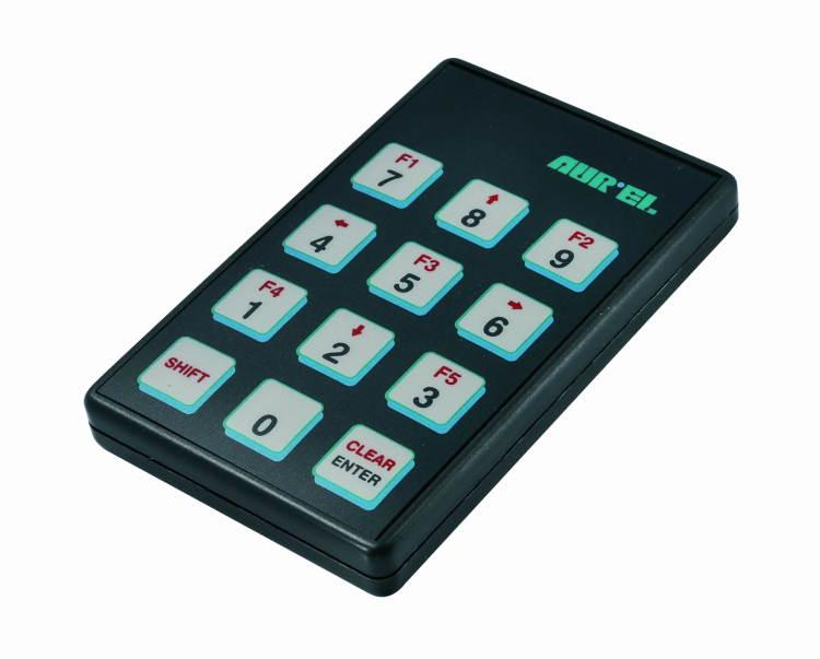
The great amount of remotely controlled devices that already are in our houses (and even beyond), made us look at the issue of having to deal with various transmitters, and consequently with what derives from that. As a first thing, you have to remember what is the purpose of each one of them, and where to find each one of them. If you limit yourself to activate an electronic lock, to command a pair of motorized rolling shutters or a gate opener, to turn the lights on and off, it may be sufficient to use a transmitter having two or four channels. If there are more systems than that, however, you need to entrust yourself to remote controls having many channels. Since it is not easy to find remote controls having more than 4 channels that are available for sale, we thought to create one that could be scalable from 8 to 12 channels, and supplied with relay outputs. In order to manage it, there is the now ever-present Arduino, that takes advantage of a RF shield, based on a hybrid receiver having a HCS Microchip decoder and an expansion with 8 relay inputs and 8 relay outputs, managed by the I²C-Bus. The Arduino based unit is the receiver, as for the transmitter there is no need to build it, since it is a ready-to-use TX handheld, and it is possible to choose it from different versions: one channel (code: HCS-TX-1), two channels (code: HCS-TX-2), three channels (code: HCS-TX-3), four channels (code: TX-4M-HCS) six channels (code: TX-6M-HCS) or twelve channels (code: TX-12CH). They are all Aurel products and can be purchased in an already assembled state at our store. We will concentrate on the twelve channels transmitter, since it allows the management of all the relays found on the expansion board. The TX-12CH contains a RF transmitter module, operating in the UHF band at the 433,92 MHz frequency, in amplitude modulation, with a power of 1 milliwatt. This is enough, when possessing a radio receiver as the one used in our system, to cover some tens of meters, even in the presence of obstacles (unless they are reinforced concrete walls). We won’t describe the transmitter’s electronics, given that it is a ready-made product: because of the technology used, it is easier to buy it than to build it. We will limit ourselves to say that it contains a HCS301 encoder, activated by a 4X3 Matrix Keyboard (4 rows, 3 columns). The system is encoded by means of a high security encoding, since it is a variable one: it is HCS by Microchip, a rolling-code system that you already learned to know in the past years, as it was used in many remote controls. It is capable of guaranteeing both the protection against the code breaking, and the command’s exclusivity, even in environments in which many remote controls, based on the same system, are operating.
The HCS shield
Our remote control’s receiving unit is implemented in a shield named RF Shield, which is based on an Aurel module as well: this one is the RX 4MHCS-4B, a superheterodyne hybrid, containing an UHF radio receiver that is tuned to the 433,92 MHz frequency, and supplied with an OOK amplitude demodulator, completed with a decoder that enables the translation of the commands sent from the transmitter. The decoding is created by a microcontroller that implements the HCS protocol and that recognizes the commands sent by the transmitter. Basically, the decoder has four output lines expressing the channel number (that is to say, the number of the button pressed on the TX) in a binary format, on a 4 bit word. Each one of the outputs is interfaced with a NPN transistor, thus the logic is an inverted one, that is to say, it is active at a low logic level; the output transistors are all configured as an open-collector. The module has an input and an output, that are respectively used for a button and to connect a LED: both are needed for the self-learning procedure. Since it is of the rolling-code kind, in fact, the remote control requires that the receiver is coupled to the transmitter, that is to say that it learns the basic part of the code and what else is needed in order to synchronize with it. We will deal with the coupling procedure later.
Clearly, in order to decode the commands a logic is needed, be it a discrete or a programmable one, and one that is operating as a 4 to 16 decoder or, as in our case, as a 4 to 12 one, since we have twelve buttons on the transmitter. In order to simplify the circuit, we left the task to Arduino: by means of the dedicated sketch, it will read the incoming data from the Aurel hybrid unit and will process them so to use them to generate the I²C-Bus commands with which it manages the relay shield.

As regards this subject, it must be pointed out that the sketch considers the management of the binary codes corresponding to the first 8 combinations, that is to say that it answers to the first 8 buttons of the TX-12CH receiver via I²C-Bus commands that are directed to the I/O Expander shield, while it recognizes the binary codes of the transmitter’s remaining keys (9, 0, Shift and Enter) as reset commands for the relay outputs, when these operate in a bistable mode. Naturally, if you feel like fiddling with the sketch, you may reassign the key codes, thus managing as high as twelve outputs.
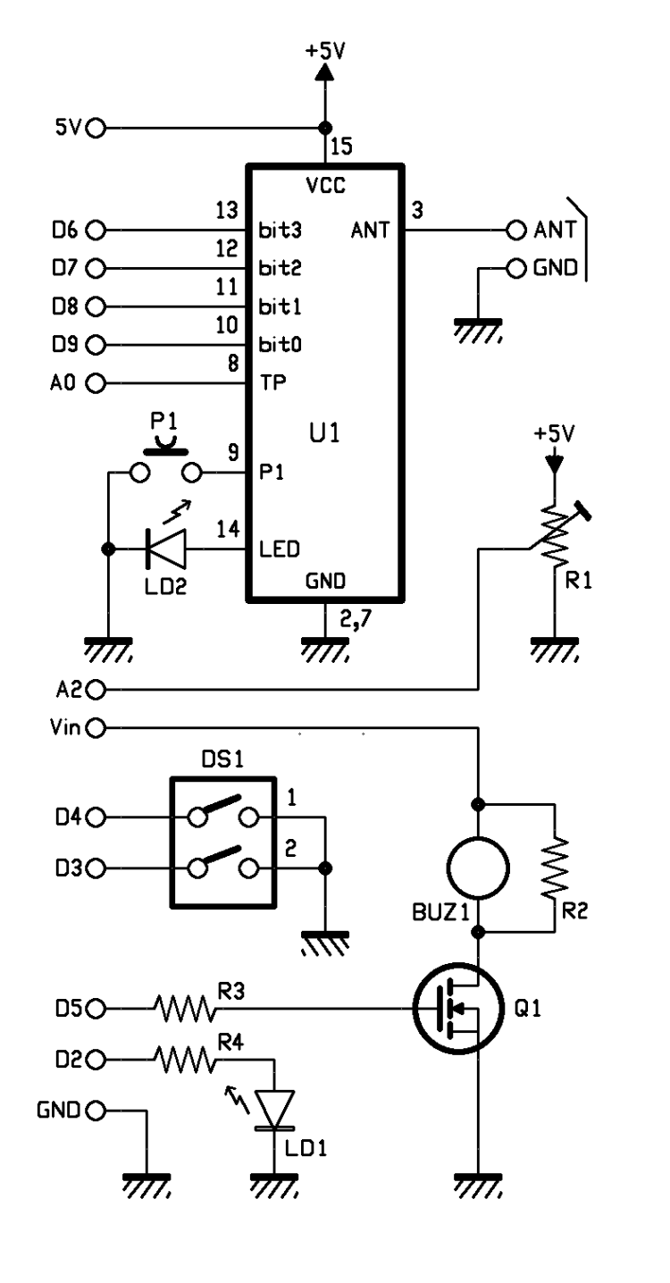
In the circuit diagram, the RF module is signed as U1 and, as you can see, it is powered by means of the 5V from Arduino, and it is surrounded by the P1 button and by the LD2 LED. The antenna contacts end on a mini block terminal that enables the connection of the receiving antenna, be it a 17 cm long whip antenna (in this case it is connected to the ANT clamp only) or an external antenna (in that case, the terminal block is connected via the shielded cable to the GND screen and the warm pole at the ANT). The four output bits and the hybrid’s TP pin respectively go to the D9, D8, D7, D6 digital pins, while the TP pin is connected to Arduino’s A0, an analog one. The latter is used in order to detect the RF’s signal strength, by operating on the basis of the fact that Aurel’s hybrid supplies (on pin 8) a voltage that is proportional to the medium frequency signal strength: from it, it is possible to infer the width of the RF signal coming from the antenna. The sketch for Arduino actually limits itself to reading this value via the ADC and to print it on the serial, so that it may be seen by means of Arduino IDE’s Serial Monitor. However, if you want to modify it, you may carry out other implementations: for example, in order to detect the reliability of the information supplied by U1, and also to understand if it is under jamming (that is to say that it is “blinded” by a 433,92 MHz RF signal that prevents data decoding); this situation may be revealed by the fact that the signal on pin 8 is strong, but that on bit0÷bit3 there is no change concerning the binary values.

In addition to U1, the shield hosts a trimmer (powered by the same 5 volts powering the hybrid), whose pointer is read by Arduino, by means of the A2 analog line (for the purpose of setting the delay time when releasing, as for the monostable delayed mode) and a LED (LD1) that is turned on by Arduino’s D2 line, when a code that is recognized as valid is received. Again, the BUZ1 buzzer (driven by Arduino’s D5 line, by means of the Q1 MOSFET) is found onboard the shield: it is simply used in order to release an acoustic note when the system is booted (by modifying the sketch, you may assign it to further functions) and the 2-pole dip switch with which to set the receiver’s operating modes.
With reference to table, let’s see the dips’ significance: dip 1 is the one defining if the shield’s relay outputs have to operate in a bistable or astable mode: when it is OFF (open), all the channels – every time they receive a command – change their condition with respect to the previous moment, thus if a relay is at rest it will be energized, while if it is energized it will return to a sleep state. By closing dip 1 (ON), all the outputs will be pulse operating. At this stage, it is the dip2 to decide how the astable function is to be managed: if it is ON (closed) each relay will follow the transmitter’s button; this means that if we press the 2 button on TX, RL2 will spring into action and will remain energized until we release the said button. Actually, by keeping a button pressed, TX will transmit for a maximum of 25 consecutive seconds. In this mode, only one relay at the time can be activated. If, on the other hand, dip 2 is set to OFF (open), the relay outputs will be activated as soon as the corresponding button on TX is pressed, but – by releasing the latter – they will not return immediately to a sleep state and they will do it instead, only once a time interval (as set via the R1 trimmer) has passed.
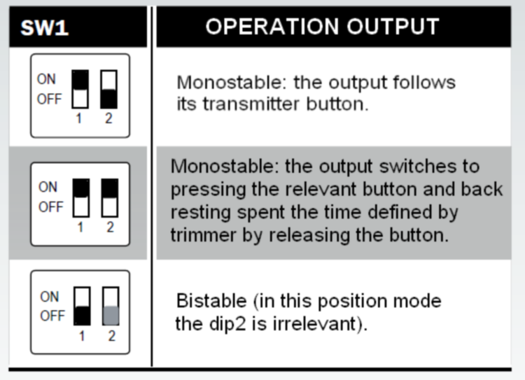
The delay time when releasing the relay is equal to the value read by Arduino’s A/D converter (0 at zero volts and 1,023 at 5 volts) from the trimmer’s pointer: it is expressed in milliseconds, multiplied by 5. Thus, with the pointer being completely towards the end connected to ground, the delay is null (the relay will drop once the transmitter’s button is released) while with the pointer halfway (2.5 volts), the delay is 2.56 seconds since ADC’s reading is theoretically 512; if the pointer is brought completely to the end connected to the +5V, the delay reaches a maximum, that is to say 5.12 seconds.
The I/O Expander Shield
That said, let’s move on to rapidly analyze the I²C I/O Expander shield, a circuit that we already used in other project, and of which we relate the circuit diagram only; the shield is based on the MCP23017 (signed U1) integrated circuit, produced by Microchip: it is an I/O Expander having a total of 16 GPIO pins (split into two ports, named A and B) that can be individually configured as inputs or outputs.
In our diagram we decided to set all the 8 pins from the A port as outputs, while the 8 pins from the B port were set as inputs. The outputs end on the U2 ULN2803 integrated circuit, a component that has been specifically projected as a driver for the relays (inside, it has different transistor stages available: they allow to drive the relays’ reels without problems). The inputs, on the other hand (B port) are connected to dedicated circuit sections that realize the digital inputs. We would like to point out that they are not used in the application described in this article, but for clarity purposes we will analyze them all the same, since they will surely turn out to be useful in future projects. Each input has a protection diode, a pull-up resistor and a LED. When the input is at a low level (at ground) the corresponding LED is turned on, while the I/O Expander will indicate that the input is at “0”; vice versa, when the input is at a high logic level, the corresponding LED is turned off and the I/O Expander will indicate that the input is at “1”.

The MCP23017 management is carried out via I²C Bus protocol and writing/reading of specific internal registers.
As is known, the I²C bus is created from the SDA lines (that is to say, the data ones) and SCL lines (clock); on the integrated circuit they are available on pins 13 and 12 and, as shown by the diagram, they are brought on the corresponding pins in Arduino board.
MCP23017 offers the possibility to generate an interrupt, in the wake of the variation of at least a pin that has been programmed as an input; in our case we didn’t take advantage of this function, however it may be useful in order to manage the inputs in interrupt (and not polling) mode (which ensures more speed, without burdening the I²C bus), from Arduino. Clearly, in order to take advantage of this feature it is needed to opportunely write the firmware.
In the shield we considered the possibility to bring (via jumper) the MCP23017’s interrupt pin (INTB, pin 19) as an input on two different Arduino pins (D2 or D4), so to adapt it as much as possible to the actual usage.
The I²C-Bus’ address for the MCP23017 is selected via SW1 dip-switch; there are 3 dips in it, thus it is possible to connect up to 8 different shields, without interferences among them.
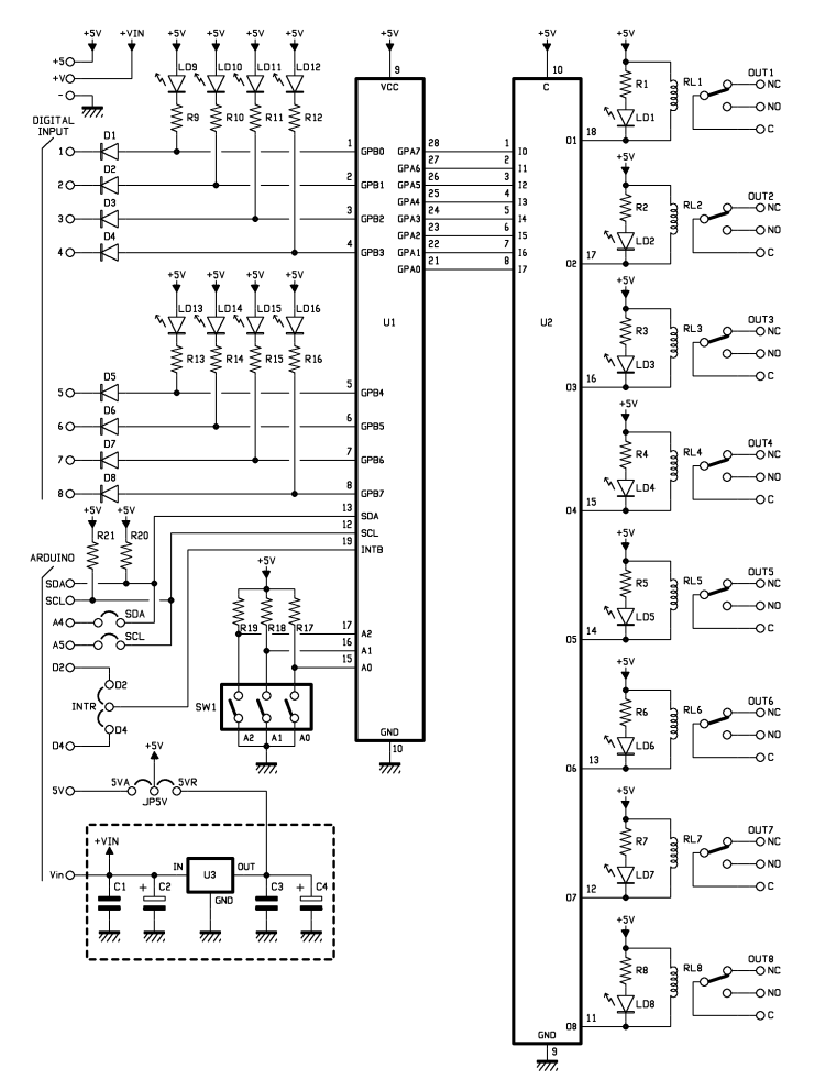
Finally, a power source section is found, and it is composed by the U3 regulator (L78L05 integrated circuit) that converts the Vin input voltage into the 5 volts needed in order to operate the whole circuit. We also point out that by means of the JP5V jumper it is possible to choose to bypass the regulator, and to directly use the 5V supplied by Arduino board.
Arduino libraries
In order to manage the I/O Expander shield, an Arduino library has been provided: it supplies all the routines that are needed in order to detect the connected shields, and the relative I/O management. The communication with the MCP23017 is based on the I²C-Bus, thus the library uses Arduino’s “Wire.h”. There is a “begin(int i2cAddress)” function, in order to initialize the single identified shield via I²C address, and even an “init()” function, so to correctly program the chip’s internal registers according to our needs; and finally a “pinMode(int pin, int mode)” function, so to indicate if the single I/O pins are inputs or outputs.
In addition to the initialization functions, the instructions we are interested in are: “digitalRead(int pin)”, “digitalWrite(int pin, int val)”, “digitalWordRead()” and “digitalWordWrite(word w)”. Respectively, they enable the reading of an individual input pin’s state, the writing of a single output pin’s state, the reading of all the input pins’ states (in our case, they are eight), and finally the writing of all our output pins’ states (and they are still eight).

As anticipated, the inputs management may happen via interrupts; there is therefore a dedicated function, “pinDisableINT(int pin)”, that enables the configuration of a single pin as an interrupt generator or not (in certain applications it may be useful to have the possibility not to set all the input pins as interrupt generators, and to do it in a selective way).
As for the HCS shield, it does not require libraries, but it is directly managed from the sketch.
How to use it
Well, at this stage all that remains to do is to program the remote control and put it to the test: once you are in possession of the transmitter, please power Arduino and then verify that all the I/O Expander shield’s relays are in a sleep state, and that the LEDs are turned off. To ensure that the receiver may answer the transmitter you are in possession of, you have to couple the two items, it being understood that TX and RX must have the same manufacturer’s code, since otherwise the base part of the code changes and the coupling won’t succeed. As regards the coupling, you will have to press and release the learning button (P1) placed on the HCS shield; once this has been done, the LD2 LED will rapidly flash for 10 seconds. During this time, you will have to press any of the twelve transmitter’s buttons, obviously you will still have to remain at a distance allowing an optimal signal strength (usually the learning is done on the spot). The fact that the command is sent is indicated by the LED placed on TX’s front panel turning on.
The occurred memorization of the basic part of the code and the transmitter’s synchronism are indicated by the HCS shield’s LD2, by means of a long flashing. Please notice that there is no need to repeat the operation with the other buttons, since it is enough to communicate with a single button, in order to be sure that all the other ones will be recognized. In fact, the learning acquires the basic part of the code, that is unique for each transmitter, while the part describing the buttons is the variable one. It is possible to repeat this procedure so to make the RX 4MHCS-4B receiver learn up to a maximum of 10 TX-12CH transmitters. You may also memorize transmitters having one, two, three or six channels, but please keep in mind that the button on each remote control will always activate the same relay, that is to say that it is not possible to memorize 8 single channel transmitters and to couple them to 8 different outputs.
In order to remove the coupled transmitters from the receiver’s memory, you have to carry out a total memory clear (it is not possible to delete a single code); this procedure is carried out by pressing and releasing the P1 button; afterwards, as soon as the LD2 LED starts to flash, you have to press the same P1 button again (which will cause the fixed light LED to turn on) and to keep it pressed until the LED turns off. Once P1 has been released, LD1 has to flash 5 times, in order to indicate that the code memory has been deleted. This operation is to be executed after having set up the receiver and before the coupling with the transmitter, so to remove possible accidental data that may be found in the hybrid’s EEPROM. If you have set the monostable mode with delayed release for the relay outputs, you will have to place the trimmer’s pointer located on the HCS shield in a way that will allow to obtain the desired delay; for this purpose, please keep in mind that by rotating the pointer in a clockwise direction (considering the R1 trimmer in front of you) the time is shortened, while if going in a counterclockwise direction it will increase. Please keep in mind, also, that the mode and time settings concern all the outputs (it is not possible to differentiate the settings for each individual relay).
As already noticed, even though the I/O Expander shield has 8 inputs, in this application we are interested in the relay outputs only; given that Arduino does not consider them, since it does not query the shield in order to know its state, you don’t have to worry about doing anything: thus there is no need to shortcircuit them.
The project presented in these pages has been designed with the assumption that a single I²C I/O Expander shield would be used, and thus that 8 channels at most would be managed. However, since the system supports up to a maximum of 8 Expander shields, one above the other (each one has to be identified by an univocal I²C address), it is possible – in theory – to manage up to 64 outputs. In practice, since the Aurel hybrid may receive the commands from 12 channels, a second shield (whose address has to be different from the one of the first shield) is enough.
For he who would like to perform some modifications to the firmware, we related the complete sketch in Listing 1, where it is possible to see the include for the wire library, which is used for the I²C bus’ management, and the one for the library managing the I/O Expander shield. If you want to add a second shield, you will need to insert a second structure in the sketch, and naturally you will have to state the address assigned to the second shield, between brackets, in IOExpander.begin().
Listing1
#include <Wire.h>
#include <IOExpanderMCP23017.h>
const int bit0 = 9;
const int bit1 = 8;
const int bit2 = 7;
const int bit3 = 6;
const int rssi = A0;
const int buzz = 5;
const int dip1 = 4;
const int dip2 = 3;
const int time = A2;
const int led = 2;
byte puls=0;
byte rele=0;
boolean found=0;
IOExpanderMCP23017 IOExpander;
char IOExpanderAddress = 0;
void setup() {
Serial.begin(9600);
pinMode(buzz, OUTPUT);
pinMode(led, OUTPUT);
pinMode(bit0, INPUT);
pinMode(bit1, INPUT);
pinMode(bit2, INPUT);
pinMode(bit3, INPUT);
pinMode(rssi, INPUT);
pinMode(dip1, INPUT);
pinMode(dip2, INPUT);
pinMode(time, INPUT);
digitalWrite(bit0, HIGH);
digitalWrite(bit1, HIGH);
digitalWrite(bit2, HIGH);
digitalWrite(bit3, HIGH);
digitalWrite(dip1, HIGH);
digitalWrite(dip2, HIGH);
tone(buzz, 440);
delay(500);
noTone(buzz);
Wire.begin();
// <span class="hps">library</span> <span class="hps">Start </span>MCP23017
IOExpander.begin(0);
if (IOExpander.init() == true){
Serial.println(“Indirizzo 0 Ok”);
}
else
{
Serial.println(“Indirizzo 0 Errore”);
}
Serial.println(“RF Shield”);
}
void loop(){
int valrssi=analogRead(rssi);
Serial.print(“RSSI: “); Serial.println(valrssi);
int valtime=(analogRead(time)*5);
Serial.print(“Time: “); Serial.println(valtime);
// Serial.print(“bit0 “); Serial.println(digitalRead(bit0));
// Serial.print(“bit1 “); Serial.println(digitalRead(bit1));
// Serial.print(“bit2 “); Serial.println(digitalRead(bit2));
// Serial.print(“bit3 “); Serial.println(digitalRead(bit3));
ricopuls=
0;
bitWrite(puls,0,digitalRead(bit0));
bitWrite(puls,1,digitalRead(bit1));
bitWrite(puls,2,digitalRead(bit2));
bitWrite(puls,3,digitalRead(bit3));
puls=puls^B00001111;
// Serial.print(“Puls “); Serial.println(puls,BIN);
Serial.print(“Puls “); Serial.println(puls);
Serial.print(“dip1 “); Serial.println(digitalRead(dip1));
if (puls==0)
{
if (found==1){
digitalWrite(led, LOW);
found=0;
if (digitalRead(dip1)==0){
if (digitalRead(dip2)==0){ //if the dip2 is to on the relays return to standby when you release the remote control button
rele=0;
}
else
{
delay(valtime);
rele=0;
}
}
}
}
else
{
if (puls>=1 && puls<=8){
digitalWrite(led, HIGH);
Serial.print(“Button “);Serial.println(puls);
if (found==0){
if (digitalRead(dip1)==0){ //if dip 1 is off the relays remain activated as long as the remote control button is pressed
bitSet(rele,puls-1);
}
else
{
if (bitRead(rele,puls-1)==0)
{bitSet(rele,puls-1);}
else
{bitClear(rele,puls-1);}
}
}
found=1;
}
else
{
rele=0;
}
}
Serial.print(“rele “); Serial.println(rele,BIN);
gestrele();
}
void gestrele(){
for (int i=0; i<=7; i++)
{
int staterele=bitRead(rele, i);
IOExpander.digitalWrite((15-i),staterele);
}
}
From Open Store
I/O expander shield for Arduino
Receiver 4bit digital decoding
