Microsoft Kinect for Xbox revealed itself as an excellent scanner, with which to acquire the shape of items. Let’s see how to use it along with ReconstructMe, that in its more recent versions allows the creation of models that are accurate and ready to use.
The scan of solid objects, better known as 3D scanning, allows to obtain computer models with which to create virtual digital scenarios, characters to integrate in animations and videogames, but also and especially files to be used for 3D printing and for manufacturing via CNC milling machines.
Ever since 3D printers have been spread to the general public, to scan a face, a bust, but also any object has become an ambition of many hobbyists; but unfortunately the machinery to do it (that is to say, the 3D scanners), is very expensive and undoubtely beyond the means of the common user. In these pages we propose to actually use the Kinect (the motion sensing device for Xbox players) to acquire the shape of the objects via appropriate programs, that are even freely available on the Internet.
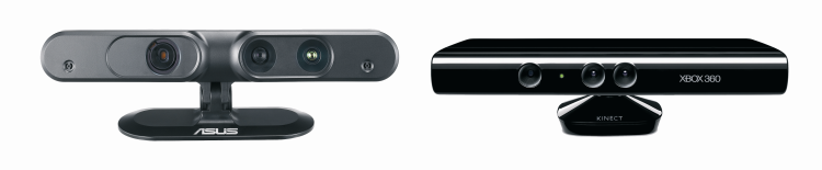
Microsoft Kinect and its alter-ego, produced by Asus.
The Kinect
Even though it is marketed as a “sensor” for Xbox, the Kinect is something more than that, in fact it contains a RGB video camera, featuring a 640×480 pixels resolution; and coupled with an additional video camera, having an inferior resolution (equal to 320×240 pixels), that is only infrared sensitive. This second video camera is used to detect the images produced by the reflection of the IR rays, projected on the scene being observed via the dedicated infrared projector, integrated in the frontal panel of the device. In addition to the video sensors, in Kinect a triaxial accelerometer is present, to detect possible vibrations and movements to which it is subject to. But that is not all, since Kinect makes four microphones available: they are radially disposed, used, taking advantage of the reflection of the sonic waves within the room, for the calibration of the environment it is in. With such a solution it is possible to filter unperceivable echoes and background noises during the usage of voice commands, so to allow voice commands to be really effective and immediate. In addition to having such an extent of sensors, Kinect integrates an engine, used to make it move up and down, for the purpose of better following the movements of the players. As regards the connection with the external world, Microsoft Kinect uses a similar cable, as for shape, to the USB one, from which it differs for the number of connections. In fact, the USB cable is usually composed by 4 wires (two for the power supply and the other two for serial communication), while the one of Kinect is provided of as many as 9 poles; to connect to it, it is therefore necessary the use of an adaptor to provide the auxiliary power supply at 12 V, in addition to the normal USB connections.
To use Kinect as a 3D scanner, the hardware needed is just the one concerning the video cameras, the infrared projector and the accelerometers.
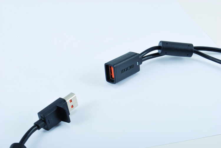
Kinect’s connection cable looks like a USB one, but it is not: it must be connected to the female of the USB cable supplied with the device, that ends on the other side on the network power supply.
Kinect works like this: the infrared projector casts in the space before it a very accurate pattern, made of a multitude of equidistant points. By analyzing the image obtained by means of the camera that is sensible to such IR rays, Kinect determines the distances among the various points, thus obtaining distance and inclination of the lighted object. Since the IR beam starts from a limited area and broadens as the distance grows (it is roughly conical…), where the dots appear to be very close, it means that the object is close to the sensor, vice versa, if the distance among the points is remarkable, it means that the object is located farther. By summing up all of the information, it is possible to obtain the spatial configuration of the surroundings, that is to say, the shape. To understand the thing better, imagine to lay a polka dot sheet on an object standing on a surface: it is possible to identify the shape of such an object on the basis of how the dots are disposed, as the sheet wraps up the item itself.

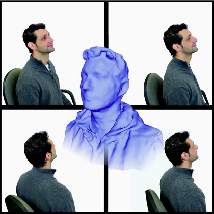
The area scanned by Microsoft Kinect: to shoot a person, the manufacturer advices to keep the device at a distance of 1,8 meters from him; less is needed for the busts.
How to acquire a scan with Kinect for Xbox 360
Let’s see how to use Kinect for Xbox 360, to acquire images and create 3D models; we need a Personal Computer with an accelerated graphics card by ATI, Nvidia or Intel, and the ReconstructMe program with the appropriate drivers for the sensor used. This is not an open source solution, but a program freely made available and with limitations for non commercial usage, while a paid license is needed for manufacturing and professional purposes.
With ReconstructMe it is possible to use, as an acquisition sensor, the Xtion Pro device by Asus, or the other ones described by the program’s website.
As a scanning example, we will explain how to shoot the bust of a person and then print it in 3D.
Let’s start from the remark that, since Kinect has been designed to acquire the whole figure to detect its moves, the optics and the firmware producing the depth data have been calibrated on a volume. The Kinect allows even the recognition of facial expressions, rather than the one of some characteristics of the face itself, given that the definition of the depth map is 320×240 pixels. This is a very demanding approach, however, from the point of view of the calculations, and in fact the developers at ReconstructMe have thought to take advantage of the graphics processors on board of the video cards, to have a result that could be acceptable in terms of frames per second. The software, in fact, has to deal with the tracking of the objects, adding the new measures to the cloud of dots, and associating them to the previous ones. In practice, when a subject rotates, the software recognizes the structure of the surface that has already been acquired, even in the new depth map, and therefore manages to “connect” the common dots, while it adds up those that have not yet been managed.
The usage of the GPUs of graphics cards implies some compatibility limits, and in fact along with the software a compatibility list is supplied with the various graphics cards. The software has two operating modes: a normal one (Standard, with a 1x1x1m volume, subdivided in 256 elements for each dimension) or a high resolution one (Hi-res, with the same volume, but with 512 elements). The operation of the compatible cards is not guaranteed for both modes.
How to install the necessary software
To create our 3D model, we need to have installed the ReconstructMe software and the SDK for the Kinect. This last one can be downloaded from the Microsoft website (www.microsoft.com/en-us/kinectforwindows/), that supplies a series of drivers that allow to use the various Kinect versions. ReconstructMe can be downloaded from the website at the address http://reconstructme.net, by clicking on the download button that can be seen on the left of the corresponding page; the software includes a series of predefined profiles. In practice, download the file with the .msi extension and proceed with the installation; the installer of ReconstructMe will essentially ask you a directory in which to install everything.
The version of ReconstructMe that can be freely used (we tried 2.1) shows a limitation: the file produced by ReconstructMe is “tarnished” by the program logo and by a series of spheres arranged as a net around the subject; but don’t worry about this, because we will explain how to obtain a “clean” subject.
As for the part concerning the video card, you must have some drivers supporting OpenCL and it may be a good idea to check the website of the card or computer manufacturer, to download the most recent drivers. As indicated in the compatibility table (Table 1), only some video card models have such drivers, for other and more recent ones this is not certain and it is convenient to check the dedicated section of the website, that is periodically updated.
If your video card is not in the list but supports OpenCL, try to use ReconstructMe in the two available modes, to discover what works and at which frame rate you may operate.
Possibly, try to experiment with the modification of the parameters of the configuration files, by following the indications of the documentation that is available on the website, maybe by defining a different scanning volume.
| Chart Legend | ||
| Smooth realtime experience | ||
| Jerky realtime experience | ||
| Does not work at all | ||
| Model | Standard | Highres |
| ATI FirePro V3800 | 3 | 1 |
| ATI FirePro V4800 | 3 | 1 |
| ATI FirePro V5900 | 3 | 3 |
| ATI Radeon HD 2600 Pro | 2 | 1 |
| ATI Radeon HD 4570M | 1 | 1 |
| ATI Radeon HD 4870 | 1 | 1 |
| ATI Radeon HD 5145M | 1 | 1 |
| ATI Radeon HD 5650M | 3 | 2 |
| ATI Radeon HD 5700 | 3 | 3 |
| ATI Radeon HD 6490M | 2 | 1 |
| ATI Radeon HD 6570 | 3 | 2 |
| ATI Radeon HD 6850 | 3 | 3 |
| ATI Radeon HD 7640G | 2 | 1 |
| ATI Radeon HD 7850 | 3 | 3 |
| INTEL Dual Quadcore | 2 | 2 |
| INTEL HD Graphics 3000 | 2 | 1 |
| NVIDIA Geforce 9500GT | 2 | 1 |
| NVIDIA Geforce 9800GT 3D | 3 | 3 |
| NVIDIA Geforce 9800GTX | 3 | 3 |
| NVIDIA Geforce G 102M | 2 | 1 |
| NVIDIA Geforce GT 240 | 3 | 2 |
| NVIDIA Geforce GT 330M | 2 | 1 |
| NVIDIA Geforce GT 430 | 3 | 3 |
| NVIDIA Geforce GT 440 | 3 | 3 |
| NVIDIA Geforce GT 555M | 3 | 3 |
| NVIDIA Geforce GT 630M | 3 | 3 |
| NVIDIA Geforce GTX 220 | 2 | 2 |
| NVIDIA Geforce GTX 280 | 3 | 2 |
| NVIDIA Geforce GTX 295 | 3 | 1 |
| NVIDIA Geforce GTX 460 | 3 | 3 |
| NVIDIA Geforce GTX 550Ti | 3 | 3 |
| NVIDIA Geforce GTX 560 | 3 | 3 |
| NVIDIA Geforce GTX 560M | 3 | 3 |
| NVIDIA Geforce GTX 570 | 3 | 3 |
| NVIDIA Geforce GTX 590 | 3 | 3 |
| NVIDIA Geforce GTX 660M | 3 | 3 |
| NVIDIA Geforce GTX 670M | 3 | 3 |
| NVIDIA Geforce GTX 680 | 3 | 3 |
| NVIDIA GT 540M | 3 | 3 |
| NVIDIA Quadro 2000 | 2 | 2 |
| NVIDIA Quadro 3000M | 2 | 2 |
| NVIDIA Quadro 4000 | 3 | 2 |
| NVIDIA Quadro FX 2800M | 3 | 1 |
| NVIDIA Quadro FX 3500M | 3 | 1 |
| NVIDIA Quadro FX 4800 | 3 | 3 |
| NVIDIA Quadro FX 580 | 3 | 1 |
| NVIDIA Quadro NVS 140M | 1 | 1 |
| NVIDIA Quadro NVS 295 | 2 | 1 |
| NVIDIA Quadro NVS 3100M | 2 | 1 |
| NVIDIA Quadro NVS 4200M | 2 | 1 |
Compatibility of the most common video cards with OpenCl: 1) not supported; 2) produces a visualization with superficial anomalies; 3) produces a smooth visualization.
How to Scan
To obtain some good scans, it is necessary to mount a “location” with specific characteristics. It must be said that, in comparison to the versions of the past, the most recent ones (and therefore the one that can be downloaded from the website at the moment of the writing of this volume) can be more easily used, and allow to carry out the scan by yourself: you just need to sit on a rotating stool, and to place Kinect on a stable tripod, so that it is standing at the height of the face or, in any case, of the bust. If you have to shoot an object, use a rotating disk or the usual rotating stool, and place Kinect before the object itself. It will be better if the stool can be adjusted as regards the height, so that it is possible to try to scan the subject from two different vertical angles. The stool should have the most neutral and flat situation behind it (a somehow distant wall is ideal).

Positioning of the subject before Kinect.
A specific lighting is not needed, since Kinect actually carries out the acquisition by analyzing the light produced by its own infrared projector, and reflected on the surface of the figure. Some preliminary test will allow the user to become familiar with the scanning system, with the volume managed, with the subject’s rotation speed and with the commands that ReconstructMe allows to give. Finally, the subject should avoid to wear garments with a poorly defined surface, such as a very soft wool sweater, or a fur collar; moreover, the subtle details (such as glasses frames) are not detected, while sunglasses with dark lenses and a thick rim will be. Generally speaking, remember that the depth is managed by projecting a very complex and dense dot matrix, with the infrared light. When something is not reflected in a clear way, the matrix will consequently create acquisition problems.
By starting ReconstructMe a window will appear, that represents the graphic interface, on the left of it the commands are shown: “Device” opens a dialog window from which to choose if to let the computer to automatically detect the acquisition device or (by deselecting the option button “Automatically detect sensor”) to manually select the relative driver (with “Browse” you may select the path of the relative driver).
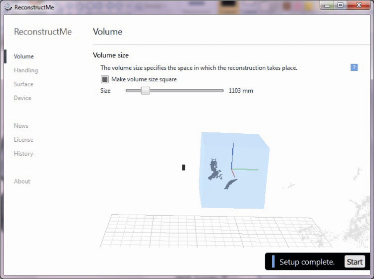
The “Volume” command opens a window that visualizes a cursor with which to define the dimensions of the area in which to start the scan. “Surface” opens the window from which to define if to have a colour scanning (to obtain a 3D printing model, this option must not be selected) or, if you wish to obtain a model with settings for 3D printing, this is the option for you to choose, so select “Selfie 3D Scan”.
ReconstructMe’s user interface (version 2.1).
To start the scan, you just need to click on the “Start” button, placed down and on the right in the main window; at this stage the computer will emit a series of beeps, that will invite to make a choice. Once the sounds have stopped, the scan starts and it is necessary to start to slowly turn while on the stool, until a rotation has been completed: the program will detect that and will emit a combination of different notes to communicate that it has shot the whole surface of the subject. Please notice that the time needed to put yourself in position may be defined by clicking on “Handling” and then by dragging the “Start Delay”cursor with the mouse; if you change it, you will notice that once you click on “Start”, the duration of the series of acoustic notes will change.
The most important point of view in this phase is to find a position in which the sensor operates at its best, and manages to produce reasonable details of what has been framed. Practice by trying to rotate the subject being taken, and by shooting from different vertical angles. The minimum distance to position the subject is about 70 cm, also considering the fact that Microsoft advices, for Kinect, a distance from the player whose movements will be detected, typically 1 meter and 80 cm.
The subject must rotate with the stool, at a possibly constant speed, and not too quickly (a round in about ten seconds is fine).
Repeat this operation to produce two or three versions of the subject, and choose the one that came out the best.
Each complete scan shows the result in the dialog window of the graphic interface; down, the message “Surface updated” tells that the scan is complete; if the result pleases you, click on “Save”, otherwise repeat the scan with “New Scan”. The save generates a file with the .ply extension, to which you will have to assign a name and a path to place it, under the request of the program.
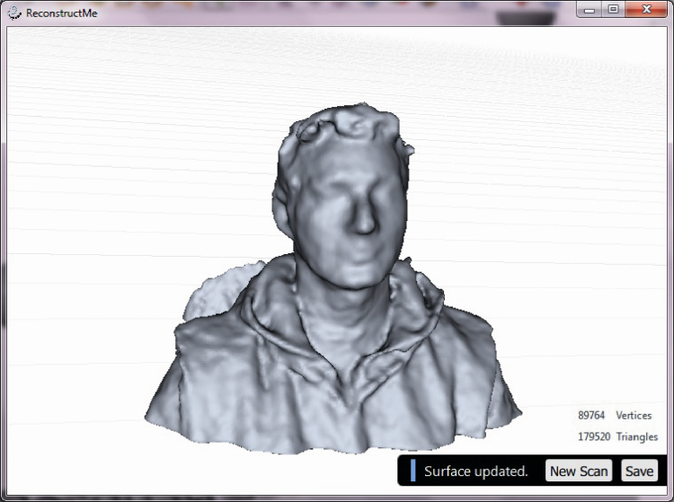
The result of the scan made by Kinect.
File conversion
The file obtained with this procedure cannot be printed in 3D, at least before it is processed and then converted in STL via Meshlab; this last software is freely available for download.
The first thing to do after having installed the program is to launch it and to open the .ply file (with the File>Open command) containing the scan; something like what can be seen in figure will appear.
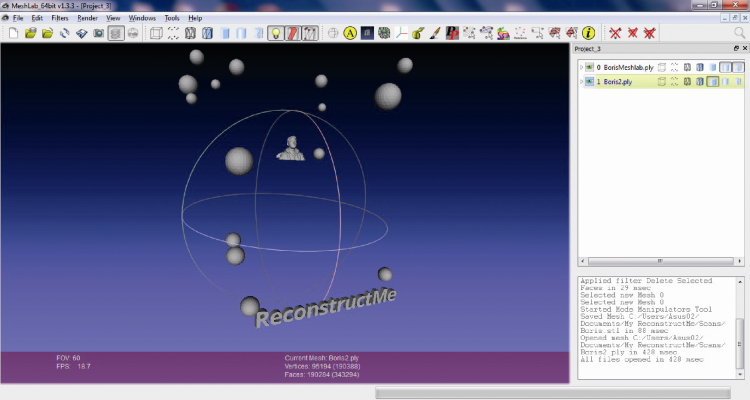
Retouching the .ply file generated by ReconstructMe with Meshlab: please notice the logo and the spheres that “tarnish” the subject. The arrow indicates the icon of the “Select Connected Components in a Region” command.
Now you have to clean the image to leave the subject only; this is obtained by clicking on the “Select Connected Components in a Region” icon (the same command can be given via the Edit Menu) and by defining with the mouse the area that we want to keep.
Once this has been done, from the “Filters” menu click on “Selection” and give the “Invert Selection” command from the submenu that just opened; in this way it is possible to select all the unrelated elements, all at once (otherwise you would have to select them one at the time with the mouse and to delete them individually). By pressing the “Canc” button, you may now delete the unrelated parts and you will see the only shot subject to remain on the screen.

The selected area in Meshlab.
You may now save the file by exporting it as a STL file (File>Export Mesh As command). Please notice that, even if Meshlab has a filter (under the “Filters” menu) to “close” the gaps in the model, they are not needed since the version of ReconstructMe that is available since a year now automatically provides to generate already sealed .ply files from which to obtain printable STL files, without errors turning up.
On the other hand, we may use a filter to smooth it (Filters>Smoothing), if the model looks a bit angular, as if we had used some sandpaper.
It is possible to further develop the model obtained, by means of a program like Sculptris that allows, for example, to refine the split parts (sometimes protuberances like a nose may appear split in the scan with Kinect) or reliefs that are mistakenly created during the scan, in other words, to add and to shape elements as if working with clay.
The model obtained from Meshlab can already be printed and, since ReconstructMe generates files that already contain their own basis, in theory there is no need to cut and square it to obtain the starting basis of their 3D printing’s first layer. However, if you wish to cut the model at a different height, you have to open the .STL file with Netfabb Studio, and you may place the support base at the desired height, and eventually correct the orientation of the model.
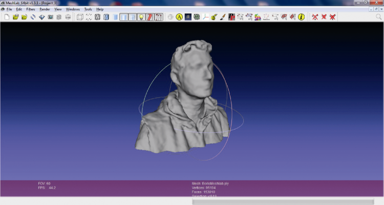
The bust, after the deletion of the logo and the spheres created by ReconstructMe.
The orientation is needed because of the fact that, during the scan, it is easy that the subject was not properly keeping a straight back, but rather a curved and bent one, probably because to stay motionless he chose a comfortable position. With Netfabb it is possible to correct the stance, by rotating the model of a certain number of degrees on the X axis, remembering that if the chin does not appear horizontally aligned, but it is slightly bent upwards, it will be possible to print without supports, while if it is straight, it is necessary to activate the printing supports.
Always by using Netfabb Studio, it is possible to further modify the model, by means of the repair function; this is not needed if you use the .STL file generated by Meshlab, but in the case you operate with Sculptris and by mistake you create a hole on the surface of the piece. By using an exclamation mark, Netfabb Studio warns about the existence of potential printing issues: in this case, the software will automatically propose the repairing, during the export phase (the repairing can be done with an online service made available by Netfabb Studio). Only after the slicing is done, however, you will know if everything is alright or not.
Adapting the scan to the print
With the STL file, it is possible to get on to printing via Repetier Host. If you already acquired the model with the Selfie 3D Scan setting, the model can be print immediately with your 3Drag, since it will be at most of the size of 20x20x20 cm. Without such option being set, the model may be bigger of the maximum printable volume and in this case Repetier-Host will present it with a “warning” colour, and will make it pulse (in such a case, use the resize function and set the scale so to make it fit the allowed dimensions).
Use the “Center object” buttons to put it in the center of the print plate. The rotation to make the bust “stand up” is 90 degrees on the X axis. Please repeat the centering and the alignment. With the bust correctly placed, you may work on the reduction percentage in order to obtain the best result. Depending on the appearance of the subject, in fact, you may have different dimensions and proportions.
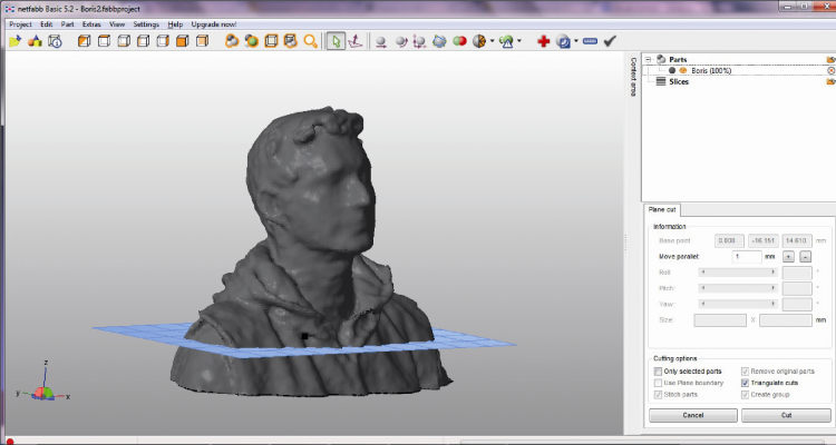
Cutting the basis of the bust at a different height from the original one, in Netfabb Studio.
Please inspect the model to be printed, by using the video camera rotation function around the plane (the first icon up and on the left, the one having a circular arrow) and above all pay attention to the inclinations on the back of the neck and under the chin, to understand if there are potential printing issues. The following step, the one concerning the slicing, may require even fifteen minutes, given that the model will surely have a high number of triangles. As regards the settings, we advice you to limit the perimeters to a number of 2 or 3, and to keep the fill at a moderate value, such as 15 or 20%, to not lose too much time when filling the bust. At the end of the slicing, we suggest you to inspect again the final result and to verify that in the critical areas concerning the back of the neck and the chin there are no perimeters that lay on nothing. If you find any, you may decrease the thickness of the layer, thus increasing the printing time, however; or you may return to NetFabb Studio to modify the bust’s inclination and the consequent angle of the back of the neck or of the chin.

Printing settings in Repetier-Host.
From the store

[…] är ett kul exempel på hur man kan använda Microsoft Kinect för att 3D-scanna in objekt. Väldigt prisvärt sätt, eller vad tycker […]
[…] 3D Scanning with Microsoft Kinect […]
[…] 3D Scanning with Microsoft Kinect | Open Electronics – 3D Scanning with Microsoft Kinect. … To use Kinect as a 3D scanner, … to have a result that could be acceptable in terms of frames per second. The software, … […]
[…] Source: 3D Scanning with Microsoft Kinect | Open Electronics […]