Based on RandA, this machine can prepare cocktails, by drawing the quantities from dedicated dispensers, according to recipes dowloaded from the webpage from which the drink has been requested. Learn more in this first post.
If one has the possibility to relax and maybe doesn’t have to get behind the wheel for a while, the evenings outside call for cocktails that will combine the pleasure of the alcohol with the refreshment coming from some ice cubes. If we go to the bar, we’ll find a bartender juggling with the tumbler, so to serve us our favourite drink. On the other hand, if we are at home with friends, we have ask to a friend who is adept at preparing drinks, or to roll up our sleeves and get down to do it ourselves. There is also a third possibility, indeed a futuristic one, but one that has already been experimented in some clubs, pacifically “invaded” by robotics: to rely on a cocktail-making machine. Things like this do exist in the professional world, but can also be self-built, by showing our determination as makers and by browsing the pages of Elettronica In! In fact, we saw a similar machine at work and, conquered by the wish of having a perfectly mixed cocktail with the right ingredients, we got down to it and we built a robot capable of doing it.
Thus Drink Maker was born, a project that can be carried out with some initiative by him who knows how to practise with mechanical parts, and naturally with electronics. It is also available in a version that can be assembled, however, for those who want to recreate their own technological corner bar at home, and to amaze their friends by making them “order” their favourite cocktail from the smartphone or the PC, so to see it prepared live by the robot.
The project

The shield creates the interface between Randa and the electromechanical part of the machine.
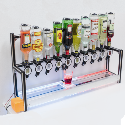
Our robotized drink-making machine is a chassis composed by aluminium extrusions, upon which dispensers are applied in a row: they are activated by a rear button, pressed by a lever commanded by a servomotor. Each time it is activated, each dispenser supplies a predetermined drink quantity, in our case corresponding to 2 cc (20 ml). Each dispenser is mounted upon a bottle carrier, that allows the insertion of the nozzle as gasket in the bottle neck, so to give stability to the whole.
The whole stays on the machine’s raised part, fixed at the base on which the mug holder cart runs on the axis in a linear way. It runs by means of some ball casters on the cavities of the aluminium extrusions, that are longer than the chassis. Behind the cart a servo control that activates the dispenser is fixed as well, thus each time the cart brings the glass under a dispenser, this last one is activated and pours his dose for the number of times set by the system. To avoid that the cocktail is shaked up to the point of pouring the fluids out of the glass, during the passage from a dispenser to the other one, we saw that the cart’s speed changes in a progressive way, by starting out slow to reach the top speed after about a second, and then to slow down up to the point of stopping, after another second. The cart’s movement is achieved by means of a dented belt that bites a pulley (also dented), and activated by a stepper motor placed on the inferior part of the chassis. The motor is managed by a dedicated controller and lined to the start on the basis of a limit switch that has been placed all to the left, and that is stimulated by a specific protrusion of the cart. The beginning of the course corresponds to the first dispenser, thus during the building phase of the machine you have to make sure to place the limit switch so that its lever is pressed when the cart has the glass centered in respect to the first despenser’s nozzle.
In order to make it possible for the mechanics to carry out what has just been described (that is to say to bring the cart with the glass under the bottles needed to prepare the required cocktail, and to receive from the dispenser the drink quantity that has been indicated), a quite refined electronic control is needed. In our case, this is achieved by combining Raspberry Pi, our RandA board (a bridge between Raspberry Pi and Arduino), a specific shield and a motors driver, and in the end this is the same that has been used for the 3D 3Drag printer’s project. The whole sequence of the movements needed to prepare a cocktail and to bring the glass containing it back (to the beginning of the machine so that it can be picked up), is decided on the basis of the composition of the cocktail itself. This one is chosen by the user by means of a customizable web interface. Thus we have a part of the electronics that enables us to choose the cocktail from a database (previously prepared by the system manager and that can be composed at leisure). Another one translates the ingredients of the cocktail itself in mechanical movements (moving the cart, pressing the dispenser’s button…). Finally, another part physically controls – by following the corresponding instructions – the step by step motor and the servo control to operate the appropriate actions.
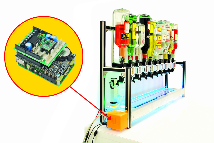
The entire electronics takes place in the container printable 3D, to be fixed to the side of the frame and from which come the cables and connections of Raspberry Pi.
In particular, in the electronic section of the machine:
- Raspberry Pi generates and governs the user web interface, works as a host for the cocktails’ settings, manages the auxiliary functions such as verifying that the order can be satisfied on the basis of the ingredients available that compose the cocktail (it keeps memory of the quantities that have been distributed, it notices the capacity of the bottle for each dispenser). Thus, for each product it prepares the series of commands for positioning and for the dispenser’s button activation, that will then pass on to the Arduino’s section;
- RandA, that contains Arduino Uno’s hardware and the interconnections with Raspberry Pi. It receives from the latter the instructions concerning the preparation of the ongoing cocktail, that is to say the position required and the command for the dispenser’s opening button, and converts them into direct commands to the motor and servo control, then gives appropriate commands as an appropriate sequence;
- the shield interfaces the RandA board with the connections of the stepper-motor and of the servo control, with the signalling devices (we will talk about them soon), with the limit switch and more, in addition to hosting the motor driver;
- the motor driver, on the basis of the impulses received from RandA, drives the stepper motor to make it advance for the number of steps required.
More exactly, in its firmware RandA has written the relationship between the advancement needed to reach each dispenser and the corresponding number of paces that the stepper-motor has to take. For example, in the machine we created for the tests the distance between a dispenser and the following one is 97,7 mm; and the distance from the beginning of the course to the first dispenser is zero. Translating this in terms of steps, it means that the first dispenser corresponds to the starting position (thus to draw the content of the bottle therein applied you just need to command the servo that activates the button, without ordering any advancement for the cart). On the other hand, to reach the second dispenser from the first, RandA has to send 6.300 impulses to the controller, corresponding to 6.300/16 steps (because the driver is set so to execute a complete step every 16 impulses) that the step-by-step motor will have to take. The distance between dispensers, that is to say 97,7 mm, thus corresponds to 6.300/16 paces of the stepper-motor (1 step enables to travel 0,248 mm).
Thus, when it receives the order to reach the first dispenser, it translates it into motor steps and sends the number of impulses corresponding to the control lines of the motor driver, so that it may activate the stepper-motor. Once the indicated number of paces has been completed, RandA will give the order for the activation of the servomotor, that presses the button of the dispenser under which the cart was brought. Once the sequence for the positioning and dispenser‘s opening has been completed, the cart is brought back to the beginning of the course to serve the cocktail. The stop happens when the limit switch is activated, as soon as the system ends the sequence and the execution of a new order is prepared.
That’s all as regards the activation; a part that we might call a “choreographic” one has also been taken into account, as well as one for the optic signalling, as assistance for the “bartender on duty”. A LED strip based on the Philips HL1606 controller, with the lights that can be managed by SPI serial bus, is commanded by means of the shield, so to create pseudorandom lights in order to embellish the machine. At the beginning of the cocktail’s preparation sequence, however, it will flash and show a light bar that shortens itself in 10 seconds, thus indicating the time left to put the empty glass on the cart, before the preparation starts. If the glass is not put there in time, unless the process is stopped by pressing the reset button on RandA, the machine will go on and pour the content drawn from the dispensers on the bottom of the machine… And this is not good, since the wiring or the stepper motor or the limit switch can get wet.
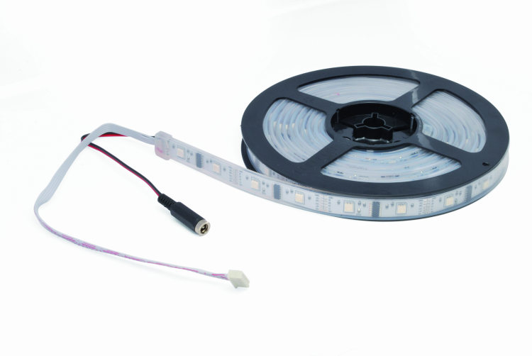
The strip of LEDs is provided with a connector to 2,54 mm pitch and takes power from a female jack wheel.
Shield’s electrical diagram

The shield carries all the connections to the machine and receives the power supply for the motor and the LED ring. The fan is mounted on the plastic container.
The circuit that interfaces RandA with the machine’s mechanics is contained in a shield on which the motor driver is mounted (for its description we refer the reader to the dedicated diagram in these pages). The shield hosts the basic connectors for the application, such as the one to connect the limit switch (STOP contacts), the LED strip (STRIP contacts), the servo control (SERVO) and a possible contact with which to subordinate the order (for example, it is applied at the output of an electromechanical token dispenser, with free contact normally open) whose connector is signed GETTON. The auxiliary connectors (CND3, CND8 e CND11, which have been reserved to possible developments: if you feel like doing it, you can do by yourself) have been prepared. The LED connector is there as well, to light the decorative LEDs to be arranged under the glass housing, so to create a play of the light. The limit switch can be NC or NO, connected between S and the positive or between S and the ground, but in our application it is NC, connected between S and ground. For this purpose, the RandA firmware sets up the internal pull-up resistor for the corresponding line (Arduino’s A3), so that when the switch is idle and closed, RandA’s ATmega receives the logical zero, while when the idle position is reached, A3 is at logical 1. The choice to use a NC switch has been imposed by the fact that the machine stops the cart and the sequence by opening it, thus if a wire is cut or detached, we are certain that the machine will stop.

A servo-control, by the lever in the figure, pushing the button from the bottom of the dispenser.
The token dispenser’s input is interfaced with RandA by means of the NPN T1 transistor, whose collector ends on the D13 line, for which it is appropriate to activate the internal pull-up; the “hot” conductor is S, while the contact can be connected between it and GND (-) o +.
On the board a relay is also taken into account, to be used for various functions (for example, to turn on a flashing light or an acoustic warning when the bottle is empty), of which the whole exchange is made available, and whose central contact can be connected internally to ground, by means of the JPGND bridge. The relay is commanded by the NPN T1 transistor, which in turn is polarized, depending on RandA’s D12 line. A diode in parallel to the RL1 reel is needed to stop reverse voltages that it will generate as a reaction at each T1 interdiction, and that may damage the collector/basis junction of the transistor itself.
As regards the connection to the STRIP, it is a sort of SPI bus: the CI line is the serial communication’s clock, DI is the output data channel from RandA and the input one for the strip, SI is not used (that can be avoided) and LI is the strobe signal for the latch which is an input to the HL1606. The communication protocol with the strip considers the bits, sent in sequence, that enable to set lighting and colour for each LED. The controller addresses up to 6 channels with a power of 30 mA each, and is capable of a colour resolution of 6+1 levels. The HL1606 chips include, within the controls set, the “automatic hue” modes for a timed and synchronized transition with some predetermined sequences, from black to a primary colour, from a primary colour to another one, or rainbow-like. In the strip, the serial control is of the essential, since otherwise to individually manage the single LEDs that compose it, many lines would be needed, even if using a multiplex matrix command. By adopting chip controllers such as HL1606, the interface is simplified to the point of counting just three lines plus the power supply (actually, it is four plus the 5 V, but we succeed at managing the controller with just three).
The HL1606 chip supports the cascade connection of comparable ones, thus allowing to create strips with a very high number of channels. Each strip controller’s output guides the LEDs with PWM signals, so to modulate the brightness in the most efficient way, and to enable all the possible colour hues.
As regards the step by step motors driver, in the shield’s plan it is signed as U1; the module is essentially an A4988 integrated circuit from Allegro, and a very adaptable one since it can be set so to define both the rotation direction of the driving shaft, and the number of degrees that the motor’s rotor has to make when receiving each command. In other words, when we give a command impulse we may decide if the module has to rotate the drive shaft one step at the time, or by 1/2, 1/4, 1/8 or 1/16 of step, depending on the accuracy we want to achieve.
Under the carriage is fixed and the chain grommet retainer strap, whose most advanced actuate the switch lever switches.
As regards the LEDs to be put under the glass, they are assembled in a ring using Neopixel technology (marketed by www.adafruit.com with the WS2812 5050 code) with 16 RGB light-emitting diodes that can be individually managed: each one of them can produce 256 tones of its colour, thus determining a total of 16.777.216 colours. Neopixel is the solution that considers the integration of a driver and of the relative RGB LED within SMD, and thus the direct command operates LED by LED. The LED scan frequency is 400 Hz, as for the strip. The data channel for communication is a serial one, of the oneWire kind, and the power supply is 5 V; the communication happens with a maximum of 800 kbps. As regards the LED ring it is possible to set the refresh frequency at leisure, so that certain types of light-games are not perceivable. More rings may be connected in cascade, to create various effects, but in this case we are not interested in such a configuration. Keep in mind, however, that the more are the rings connected to a single data channel, the more the refresh frequency will be limited, if keeping the maximum data-rate constant.

The tapster has an inlet with rubber seal multilabbro and a button by pressing which the nozzle dispenses the predetermined quantity.
The ring command protocol considers that groups made by three bytes are sent within a 24 bits string: each one of them contains the lighting status of each base colour (first the green’s eight bits, then the ones for the red, and finally the ones for the green).
The software
Having ended with the hardware analysis, we may devote some time to the project’s software. Essentially, it takes into account the software to be loaded in RandA, and the actual software, that will take place and run in Raspberry Pi. This program consists of a database and a user interface, that is divided in two parts:
- a front-end, built from the web-page that the user may see, by pointing Raspberry Pi’s IP address, and on which it operates so to make orders;
- a back-end (admin), managed by the system administrator and invisible to the user.
In turn, the Admin part is divided in three parts:
- one of them shows the cocktails being prepared, and the queue processing them (name and cocktail name, plus current state: for example it may be in the “making” phase –that is to say the cocktail making sequence has been started- or approved, that is to say the cocktail has been “approved”, since the ingredients are available);
- ingredients; select which bottles are filled, which parts (each one being 2 cl) does it contain, the slot (dispenser) position and the possibility to add more ingredients;
- cocktail composition (parts, name, possibly a picture to help the user when choosing, etc.).
The user selects the cocktail on the web interface, managed by Raspberry Pi. This last one processes the order and verifies if it is possible to make it (depending on the availability of the ingredients and also considering possible orders queued). Afterwards, if everything is ok, it will pass to Arduino the data concerning the cart’s position and the number of drink parts to be taken from each one. Arduino simply controls the stepper-motor, in order to move the cart; and the servo, in order to activate the dispenser.
The LED bar, once the procedure is started, indicates with this sort of countdown bar that we have about 10 seconds to place the glass. After that, the machine goes on with the sequence.
As regards RandA, the firmware running on it simply serves the purpose to interface Raspberry Pi, and to convert its requests into orders destined to the servo control’s activation and to the stepper-motor’s movement.
As for the servo’s management, a dedicated integrated library (found within the sketch) is used. Similarly, for the strip management there is an Arduino library for the management of the Serial Peripheral Interface (SPI) interface, with or without Latch and Sync lines.
The LED ring’s management is also transferred to a specific library, made available by Adafruit, that is the ring’s manufacturer.
Make it
Let’s move on now to talk about the machine’s construction. Its basic structure is made with square (27,5×27,5 mm) and angle (29,5×53,6×2,4 mm) aluminium extrusions, and by following the drawing in these pages. The actual chassis consists in two 27,5×27,5 mm extrusions, each one being 1 meter long. They are joined by a frame for each side, made with the same extrusions, but with different dimensions, that is, with a basis of 150 mm and a height of 330mm. Actually, the extrusions on the rear of the frames are 600 mm high. The assembly of the parts is made by means of screws, by closing each ending with the appropriate 27,5×27,5 mm caps.
In the front of the machine’s raised part, bottle supporting brackets have to be attached, by means of screws, at a distance of 97,7 mm from each other. At their bases, the dispensers have to be fixed, by means of appropriate screws; the leftmost bracket has to be exactly at 60 mm from the internal side of the upright, built from the square section (27,5×27,5×600 mm) extrusion.
The cart is a 3 mm thick, 192×100 mm aluminium slab, that has been conveniently worked by means of a CNC milling machine. A plexiglass slab of the same size is applied to it, worked so to be screwed in the underlying aluminium slab, and to host a small mug holder plate and possibly a LED ring.

The ring of LEDs is applied in the hole on the plexiglass of the carriage.
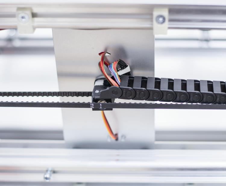
In the inferior part of the cart, on the short sides, two ball-casters with a 10 mm sphere are needed to make the cart slide along the cavities of the 1 meter long extrusions. The ball-casters have to be placed at a certain distance from the edges of the aluminium slab, so that they may slide within the cavities. The cart’s movement is achieved by fixing the belt around the pulley (on the right side) and to the stepper-motor. The same support, in addition to stopping the belt with a screw, is needed to move the lever of the limit switch. The position will be chosen, considering that the switch has to be pressed when the cart is fully placed at the beginning.
As it can be seen from the pictures, the switch has to be fixed, by means of one of the screws, with which the stepper-motor is stopped.
To avoid that fluids are poured when the cart is raised, to the 1 meter long aluminium extrusions two angle (29,5×53,6×2,4 mm) aluminium extrusions of the same length are applied. This is shown on the pictures in these pages, that is to say, with the corner on the outside.
As for the wiring, please follow the plan that has been printed on these pages: there you will find the connection of all the parts with the shield. As for the cart’s connections, please use some flat-cable whose conductors will have to pass three possible connections of the LED ring, in addition to the servo control’s connections. To avoid that the flat-cable gets entangled in the belt or that it hangs down, in our prototype we made it pass through a chain fairlead, as you can see from the prototype’s picture.
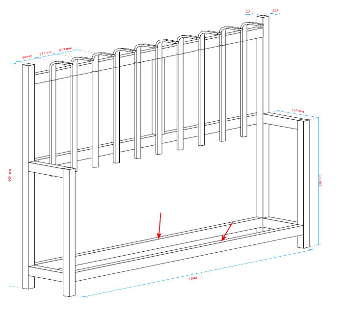
Machine frame: the 1-meter sections (arrows) must apply that limit the angular excursion of the carriage.
The electronics on board is composed by Raspberry Pi on which we applied the RandA board, that hosts the shield. We took into account that the whole would be placed in a 3D printed plastic container (with our 3Drag, if you have it at home…). Please place a small 12 V fan in it, for cooling purposes. If you apply the LED ring, please make the cable pass under the plate, by fixing it with appropriate clips, the same to be used to stop the LED strip on the angle extrusion in the rear. Once the various parts have been placed, you will have to apply the power supplies. Please remember that a 12 Vcc – 2,5 A power supply for the shield and a 5 V, 1,5 A one for RandA (that powers Raspberry Pi, by means of the inferior strips) are needed. The cables of the two power supplies have to be applied to the respective terminal box connections.
RandA’s sketch has been programmed by means of the modified IDE, that can be downloaded from our GitHub repository, and that enables loading via the network, by passing from Raspberry Pi. Thus you have to connect the latter to a PC in a network. Remember that if you want to use the LED strip as well, you will have to take into account a dedicated power supply for it, that is the one sold along with the said strip. On the other hand, a possible LED ring draws power from the shield’s 5 V line, in turn powered by RandA.
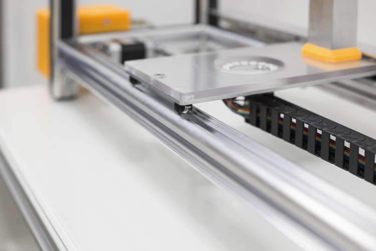
The trolley runs in the hollow of the profiled 1m thanks to ball-caster.
Before the shield is applied to RandA, you will have to open the J2 jumper on the latter: it is commonly used to enable the Arduino on-board logic to turn Raspberry Pi on and off. It has to be open in this application, also because Arduino’s D4 line is used by the shield, in order to manage the enabling of the motors controller. Please notice that before using the system, it may be needed to adjust the miniature trimmer of the motors controller. For the purpose, please make sure that the power supply is connected to the board and turned on, and take a multimeter and a very small ceramic screwdriver (it is possible to use a metal screwdriver as well, but in this case you will have to be very careful to touch the drivers’ trimmer only, in order to avoid short circuits), then set 2 V in the direct current range (or similar) on the multimeter.
Please keep the black push rod in contact with the board’s negative supply terminal, and the red push rod on the platform placed over the driver’s chip. With a ceramic screwdriver please adjust the driver’s trimmer until you can read a 0,425 V voltage on the multimeter. Once this has been done, you may take away the tester and disconnect the power supply, and then close the box containing the electronic parts.
The video of drink maker
From the store
RandA: the union from Raspberry and Arduino

What is the reference liquor dispenser (Tapster)?
https://www.amazon.co.uk/Beaumont-Metrix-Spirit-Measure-Optic/dp/B00A65JDXY/ref=pd_bxgy_201_img_2?ie=UTF8&psc=1&refRID=MBN236MDCM231FQSNMRG
It says It is also available in a version that can be assembled. But i cant find it were can you buy the kit?
what servo did you use?
Nice Projekt !
What Motor are you use for the dispenser ?
[…] perfect complement to open-electronics’ Drink Maker automatic drink “printer”, here it is the Arduino controlled whisky […]
[…] did a lot of things so far, from the 3DRag to the Chocolate Printer and the Drink Maker. Then, we moved on with RandA and later on with Fishino and its family of […]
Can I buy all except the frame?
afnuszhf
ymmslcwb
Können sie mir das image zu dem drinkmaker zur Verfügung stellen, ich bekomme das einfach nicht zum laufen
Were can y buy the drinkmaker
Is there any way, I can purchase this product? Overall, I am in love with this product. Please let me know kindly.
Hi, I am making a similar project as part of my degree’s final project. I only have a problem that I could’nt find the step file of the bottles holder and the optic measure.
I wanted to ask for the step files of those, or only the drawing file with the sizes. It would save me.
thank you in advance.