A multifunction platform built around BBC’s micro:bit educational board. It integrates a cute robot, a starter kit and also a board for experimenting.
Some time ago, in a previous article, we have reviewed the micro:bit controller designed by the BBC as an object aimed to develop logic skills and competencies in the field of computer programming for the younger grade-school students.
The initiative has been a success and several manufacturers have developed and marketed additional devices to expand the possibilities offered by micro:bit.
YahBoom’s Smart Car was particularly interesting for us since it allows to develop a wide array of typical situations for what is defined as “physical computing”, using a unique, low-cost kit.
Among the experimentation possibilities, for what concerns the micro:bit used on its own, we can include:
- managing a 5 x 5 LED matrix;
- using an accelerometer to detect and recognize different types of movement such as shaking, rotation and freefall;
- using an electronic compass capable of detecting orientation and rotation in degrees relative to the north. Another possibility might be using it as a “magnetic” metal detector;
- using two keys, pressin either one at a time or simultaneously;
- using the Bluetooth smart technology module which allows connecting micro:bit to other devices equipped with the same technology, such as another micro:bits, PCs, smartphones, Bluetooth kits, tablet PCs and cameras;
- using the radiofrequency module for communication between two or more micro:bits;
- measuring the room temperature using the built-in thermometer;
- possibility to communicate using the I²C and SPI bus;
- combining the expansion board for additional features:
- sending commands via an infrared remote control;
- generating notes and melodies using the wired buzzer on the expansion board;
- managing up to 10 mm, RGB LEDs;
- managing three additional RGB LEDs;
- on the board, we can find the reciprocate pins for the I²C and SPI bus;
- on the board, we can also find the reciprocate pins for the micro:bit peripherals which are not used by the expansion board. In particular, pins P4, P5, P6, P7, P10;
- powering using a lithium audience battery with recharge circuit integrated with the expansion board.
The additional features can be optimally used by completely assembling the “robot” kit including the motors, wheels and the ultrasound sensor. In this configuration, we have access to the additional features below:
- motor control;
- using the front sensors (infrared and ultrasound) for controlling the surrounding environment. These allow to make experiments with features such as avoiding obstacles and tracking objects;
- using the bottom infrared sensors to program a line tracker.
Finally, as a cherry on top, everything can be controlled using an Android smartphone app. Alternatively, we can use the JavaScript Blocks Editor standard development environment.
Block diagram
Fig. 1 shows the micro:bit connector pin description while Fig. 2 shows the layout of the expansion board indicating on the devices mounted on the board in their position on the board itself.

Fig. 1
A few notes about the expansion board:
- the power and recharge connector cannot be used to program the micro:bit. The micro:bit must be programming connecting the USB cable from the PC directly to the USB connector found on the micro:bit;
- the battery recharging is carried out by the LTC4056 integrated, specifically designed for recharging and keeping in charge of lithium-ion elements. The recharge status of the battery is indicated by two LED lights: a red CHA LED (indicating recharge in progress) and green LED END indicating the recharge is finished;

Fig. 2
The PCA9586 integrated, a 16-channel PWM driver, controlled through the I²C bus, interfaces all the devices requiring a PWM signal to be controlled, among which we find the two direct current motors, the two 10 mm LEDs, the line sensors, the output for the additional servo controls and for the infrared sensor to avoid obstacles. Table 1 shows an indication of which pins from the PCA9685 integrated refers to the various sensors and actuators, while Table 2 lists the connections for the micro:bit pins.
Table 1

Table 2

Building the SMART CAR
The small educational robot is provided as a partially assembled kit. The expansion board is completely mounted while the other components must be assembled before use. This way, you have nothing to solder. Keep in mind that inside the smart car box, sold by Open Electronics, the micro:bit is included.
The box, includes the following:
- 1 x micro:bit board;
- 1 x micro:bit expansion board;
- 1 x ultrasound sensor with connection cable;
- 2 x motor;
- 1 x supporting board for the ultrasound sensor;
- 2 x wheels;
- 1 x micro USB cable;
- 1 x infrared remote control;
- 1 x screwdriver;
- 4 x M3*40 copper pegs;
- 2 x M2*10 copper pegs;
- 2 x ultrasound sensor stand;
- 1 x lithium battery;
- 1 x instruction manual;
- 1 x omnidirectional broadcaster wheel;
- 2 x motor stands;
- screws and nuts.
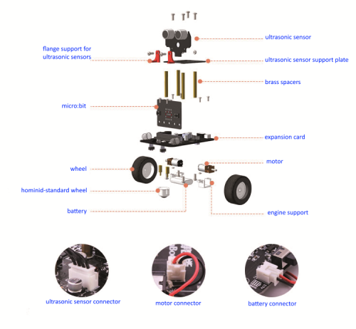
Fig. 4
Fig. 4 shows the assembly diagram which includes the following steps:
1. Mounting the motors using the dedicated white stands and the 2 x 6 mm screws and nuts (screws on the supporting board side and nuts on the motor stand side). Connect the motors cables to the dedicated connectors beside them according to the polarity;
2. Once the motors are mounted, insert the two wheels on the motor axles by pushing them (without pushing too much);
3. Place the omnidirectional ball caster and fix it in place using two 2 x 6 mm screws and nuts (screws on the supporting board side and nuts on the ball caster side).
4. Mount the four 3 x 40 mm brass pegs which are going to support the ultrasound sensor. Fix the screws on the frame side. Then, place the upper support base with the longer side towards the wheels on the smartcard. Fix the two 3 x 8 mm screws on the rear side. Place the two support flanges on the infrared sensor and fix them to the base and to the front pegs using two 3 x 8 mm screws.
5. Connect the cable to the ultrasound sensor;
6. Pass the cable through the rectangular hole on the support base. Connect it to the connector on the expansion board and finally fix the ultrasound sensor on the two flanges using the 3 x 8 mm screws and nuts. The screws go on the front side and the nuts on the side of the flange;
7. Make sure the power deviator is on “off”, i.e. with the lever towards the battery connector. Place the battery in its case and connect the cables to the corresponding connector, beside the power deviator, according to the polarity. Connect the motor cables to the dedicated connectors beside the motors making sure, once again, to respect polarity;
8. Insert the micro:bit in its connector, the red LEDs facing towards the front side of the smartcard, the one with the ball caster. The traction wheels are on the rear side.
Fig. 5 shows how the Smart Car should look in the end with each dimension. Once the assembly is complete, the first thing to do is to recharge the battery. Connect a 5 V power adapter equipped with a micro USB connector (the kind you find with smartphones), to the CHARGE” connector of the support board, with the deviator in Off position. The red LED will turn on, indicating that the battery is recharged. Once the recharge is done, the red LED will turn off and the green one will turn on to indicate that the recharge is complete. Now, we are ready to program our Smart Car for the first time.

Fig. 5
Use and programming
As anticipated in the article previously mentioned, we have different environments for programming the micro:bit, which is for the most part characterized by their web availability, without having to install software on your PC. After uploading the development environments’ applets on the browser’s cache, we can write our programs even without an Internet connection. For mobile devices, such as tablets and smartphones, freely downloadable apps are available on the providers’ stores besides the aforementioned web environments.
Before we can start, we must connect the micro:bit to our PC using the USB cable included in the package. Once connected, the micro:bit should be automatically recognized as a mass USB storage memory. If we have Windows XP, we will have to install its driver. Now, you can connect to micro:bit’s reference webpage at:
http://microbit.org/
On the main page, click on the “Let’s Code” button and you will be taken to a page listing the various program environments. In order to program the micro:bit to interact with the expansion board of the Smart Car, we have to use the JavaScript Block Editor development environment, a block development environment taking inspiration from the solution used by Scratch.
Javascript BLOCK EDITOR
Just like Scratch, it is very simple to use although it is not a toy. It allows going in-depth with structured programming and event management.
The composition method of a program entails choosing the blocks representing the instructions, dragging them to the editor panel, configure them in their customizable sections and make them “fit” correctly. This operation is made easier by the blocks’ shape. The block can be connected only if they are compatible and the shapes correspond. Clearly, this mechanism doesn’t guarantee that the logic we are going to create will be formally correct, at least from a syntactic perspective.
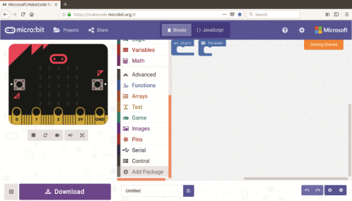
Fig. 6
In this development environment, there are also very “expressive” blocks, such as the one available for configuring the LED display. Once the programming phase is over, you can run the code you just compiled under a simulation environment, in order to carry out correctness checks, before transferring the code on the physical micro:bit. In order to activate the simulation environment, we must click on the “Restart the simulation” icon, the middle one in the bottom left corner. Once we enter the simulation environment, we can try out the various functionalities.

Fig. 7
After opening the development environment, to start programming our Smart Car, we must enrich the development environment itself using the JavaScript Block Editor extension for Smart Cars. To do that, click on “Advanced” on the left side menu, which recaps the available programming blocks libraries. In the bottom of the drop-down menu click on “Add Package” as shown in Fig. 6. A window will show up as seen in Fig. 7. Here, type in the address below:
https://github.com/lzty634158/yahboom_mbit_en
which points to the GitHub repertory containing the block library dedicated to smart cars. Once entered the address, click on the search icon which will display the “mbit” library. Click on it and the blocks will be added to the side menu bar (Fig. 8).
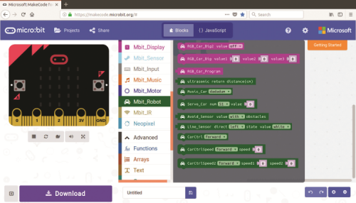
Fig. 8
A note about how the library works. Some locks included in the library make the LEDs and sensors easier to program, providing a higher level interface compared to the one requiring to set the single pins. The added value of the library is to provide different control blocks, such as those for setting the LEDs and controlling the motors, which interface with a single PWM generation pins on the PCA9685 integrated circuit. This setting allows to really expand the functions available on the micro:bit compared to it being used alone and to make it extremely easier to use. As the first example of use, we have selected an application, among those available on the smartcard tutoring site, which allows controlling how our “little robot” works by using the infrared remote control. In order to download it, go on http://www.yahboom.com/study_en/Bitbot_EN
scroll the page down to section “4 – Robot lessons”. Click on the item “9 – Infrared Control”. On the page that will show up, you can download a PowerPoint of the project and the code for the project itself. Download them both in a folder of your PC. In the PowerPoint file, you can see a short presentation where you can find the diagram on the functions assigned to the remote control.
Now, from the programming window, upload the program on the development environment, by clicking on the folder icon and selecting the “microbit-Lesson-9-Infrared-control.hex” program just downloaded as shown in Fig. 9. Click on “Go ahead” to continue.

Fig. 9
Given the documentation available for the Scratch environment and, referring to the article about micro:bit previously mentioned, we are just going to suggest some modification to program you have just opened in order to limit the smart cars speed. In every block where you can see the speed set at “255”, you must edit values as shown in Fig. 10, in order to limit the smart car’s speed of 255, which is then transformed in the duty cycle assigned to the PWM controlling the motors, making the car uncontrollable. Take this opportunity to also reorganize the blocks in order to make their layout more rational. You can see an example in Fig. 10. Done?

Fig. 10
Download the program on a folder in order to have a backup for it and then on the micro:bit’s filesystem, which should appear among the mass storage memories of your PC with its identification letter. Remember to connect the USB cable from your PC to the USB connector on the micro:bit and not on the expansion board, or you want to upload anything.
Once the download is over, disconnect the USB cable and take the remote control. The first time, you will have to remove the battery protection, otherwise… no infrared. A short description of the functions available on the remote control can be seen in Fig. 11. Key “1” turns off on the LEDs that are turned on. Key “2”, the one with the lightbulb, turns on the RGB LEDs with white light, keys “4” (“+”) and “5” (“-”) allow to turn on the LEDs using, respectively, a green and red light. Keys on the block “2”, allow controlling how to Smart Car moves. You can easily understand what the keys mean by their icons. Keys on the block “6”, from 0 to 9, on the other hand, allow showing several patterns on the LED matrix display. You can turn on the Smart car using the power deviator. Wait for the program to load and… Have fun. Of course, this is just the base on which you can build and experiment, editing this program or other example programs.

Fig. 11
From openstore

[…] Read More […]