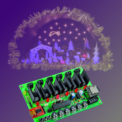
A light system, capable of simulating the alternation of night and day, that will make your nativity scene – be it a small or a big one – even more realistic. Our circuit is capable of piloting four light loads, corresponding to the daylight, to the brilliance of the stars, to the household hearths, and to the guiding star. It allows the control of LEDs and of a NeoPixel strip.
As with every year – with Christmas time approaching – we think about a themed project that might be able to make it even more original and warm. We decided to opt for a nativity scene control box, but we deemed right to make it in a modern and topical key; and with “topical” we mean the usage of hardware that has been experienced and appreciated, that is what thousands of experimenters could find in Arduino. This Presepino was born, that is to say, a light and sound control box for nativity scenes, whose circuit is based on the ATmega 328 microcontroller (therefore, that’s Arduino UNO’s hardware) and created so to directly command some LEDs, with all the relevant advantages: the first among all of them is the fact that it operates at a low voltage, and therefore it may be placed in the vicinity of children, without any danger for their health. Moreover, with LED strips being greatly available nowadays, it turns out to be very easy to create an automated nativity scene.
In addition to the lights, our Presepino enables the audio management, thanks to an innovative MP3 player module, mounted on the board, and capable of reproducing (even if in mono sound) all the tracks contained in a SD-Card.
The project
But let’s go in order and see – as a first thing – all the available functions, that differentiate our control box from those used for the simple control of two lights: dawn and sunset. With Presepino it is possible to obtain a control going beyond the one needed in small or big nativity scenes found in the houses, and one that is suitable for the nativity scenes prepared for the churches, for the parish youth clubs, for the community centres, and more in general for the places of worship. For this reason we created a circuit that is certainly a powerful one, and capable of driving four light loads, having LEDs operating at 12 volts and absorbing an individual power of 6 amperes; this is also the maximum current that the board may manage, and it can be powered by copiously tinning the tracks going from the power terminal box to the MOSFETs, and from the latter ones to the corresponding output terminal boxes. With “individual current” we mean that each channel may commute 6 amperes, but given the way the printed circuit board has been built, it is not possible to constantly absorb 6 amperes from all the outputs at the same time. These values, considering that the circuit was born for the purpose of piloting LED strips or – anyway – LED compositions, are more than adequate ones, and for a home nativity scene they are more than abundant.
The outputs for the terminal box are six, but the firmware we supply contemplates the management of the first four, so to implement the simulation of the daylight, of the starlight, of the hearths for (Bethlehem’s) hut/cave and for the shepherds’ houses, and finally of the guiding star’s lighting. The lights are progressively turned on and off, and follow a cycle that simulates the duration of the whole day.
To these basic outputs you may add the other two, by acting on the sketch for the ATmega 328 microcontroller: to them you may assign the control of various accessories in the nativity scene, such as a paddle wheel, the movement of animated characters or animals, and so on.
As regards the basic outputs, we divided the complete sequence in four phases, obviously named day, sunset, night and dawn. The duration of each phase may be independently adjusted; as for day and night, the duration is set between about 3 and 10 minutes, while the two transitions have a duration between about 20 and 100 seconds. Obviously the latter ones are the most evocative ones: during the sunset the day luminosity (SOLE output) gradually decreases, while the stars start to light up (STELLE output); at a certain point, before the cycle reaches its conclusion, the hearths in the houses and in the hut will light up (FUOCO output). By the way, our circuit is capable of simulating the flickering flames of the wood burning, by piloting the FUOCO output, by means of an appropriate sequence of pulses. When all the stars in the sky are completely lighted up, even the guiding star will appear (lighted by the COMETA output). Obviously, and except for some small details, during the dawn all the other lights will gradually turn off, while the “daylight” will reach the maximum luminosity.
The two auxiliary outputs are OUTEX1 and OUTEX2.
Circuit diagram
Let’s get down to details now, by analyzing the circuit, that is based on the ATmega 328 microcontroller, on which the dedicated sketch is running: the latter implements the control of the outputs and of the module implementing the nativity scene’s sound, and that at the initialization sets PB0 as the output used for sending the serial commands to a possible Neopixel strip, and PB1, PB2, PB3, PD3, PD5, PD6 as outputs for the control of the MOSFET outputs to channel N (the transistors are some sturdy STP36N06s, having an Id of 36 ampere and a Vdso of 60V) that materially commute the power to the corresponding LEDs or LED strips. Each one of the microcontroller’s lines that are used in order to manage the outputs also pilots its own MOSFET’s gate, by means of a 1 kohm resistor; and between the gates and ground some LEDs are applied: they allow, by lighting up, to monitor the state of the corresponding transistor. Each one of the outputs supplies rectangular TTL-compatible pulses, that have constant frequency and are width modulated, by means of the PWM technique: this enables the variation of the average value of the voltage applied by the MOSFETs to the loads related to them, and consequently, of power and luminosity. This is carried out with a very high efficiency, since the MOSFET’s electrical resistance while in ON state (fully conductive) is a very low one and thus the dissipated power (the power transferred being equal) is a very limited one, if compared to the one that would come from a series piloting that uses DC voltage, in which the transistor would have to take upon itself the difference between the power supply voltage and the one applied to the load.
The current circuital configuration takes into account to power the LED strips by connecting their positives and negatives respectively to the + and – of the corresponding output. However, since the MOSFETs may “withstand” up to 60 volts of drain-source voltages in the interdiction, it may be conceivable to start from an external power source even at 24÷36 volt of direct current, so to decrease the absorption (the electric power managed being equal). If the power is not taken from the circuit, the LED strip will have to be connected, with the + going to the chosen power supply’s positive and the – going to our control box’s output, it being understood that the power supply’s ground and the board’s one must be joined.

We previously claimed that the complete sequence that is generated by our circuit is composed of four phases (day, sunset, night and dawn), whose duration may be independently regulated by means of the dedicated trimmers, that are connected to a potentiometer and powered at 5V, and whose pointer’s voltage is read by a microcontroller’s I/O, which is configured as an input and acquired by means of the A/D converter that is found within the ATmega microcontroller. In our project, the ADC is assigned to the PC0÷PC5 lines, with which the voltages of the six trimmers (that is to say, R1, R2, R3, R4 for the said functions, and R5 and R6 for the functions that we will assign to the optional outputs – respectively being OUTEX1 and OUTEX2 – that supply PWM signals, exactly as the four basic ones do) are acquired via scan. For the way the firmware has been structured, the duration of the respective cycles is directly proportional to the voltage applied to the corresponding trimmer, thus – for example – by bringing R1’s pointer towards ground, the duration of the day is reduced, while it is instead increased by bringing it towards the 5V’s positive. The PWM signals are generated by the PWM modules that are internal to the microcontroller, opportunely set by the firmware for each output.
Please pay attention to a detail: while the trimmers R5 and R6 directly control the PWM of the OUTEX1 and OUTEX2 outputs, in the sense that they directly act on them, the other four determine the cycles’ times and don’t do it directly for the duty-cycle of the PWM signals to the SOLE, STELLE, COMETA and FUOCO outputs; the PWMs and their periodicity are managed by the firmware’s subroutines (the ones dealing with the four phases, whose functioning depending on the time is defined by the voltages supplied by the R1, R2, R3, R4 trimmers). This functioning is a logical one, since the described phases involve more than one output and, in the case of the day/night transition, they specifically involve the SOLE and STELLE outputs, that fade out – as it is also with the night/day passage.
The trimmers from R1 to R4 are thus needed in order to manage the duration of the day (R1), of the night (R2), of the dawn (R3) and of the sunset (R4). The LD6 LED is briefly turned on when passing from a phase to another one.
The duration of each single phase is set by means of the dedicated trimmer; the maximum duration of each phase is of about 100 seconds; for the sake of precision, the duration is obtained by the ADC reading on 10 bits (between 0 and 1.023), considered in milliseconds and multiplied by 100 by the firmware. If you want different times, you may edit the sketch in the section dealing with the determination of the functioning on the basis of the time.
Listing1
if(runtime>time_trim+200){
for (int i=0;i<6;i++){
trimvalue[i]=(ReadTrimmer(i));
trimvalue[i]=trimvalue[i]*100;
delay (1);
}
time_trim=millis();
}
int ReadTrimmer (int id){
return(analogRead(trimmer[id]));
}
Listing2
void gestAudio(int track){
digitalWrite (LEDPLAY,LOW);
if (playing==true){
digitalWrite (LEDPLAY,HIGH);
track++;
if (track==5) track=1;
if (stopVol==false){
if(runtime>time_volume_running+200){
if(startVol==false){
if (volume>3) {
volume=volume-3;
Serial.print(“dec “);
Serial.println(volume);
}
else
{
playtrack(track);
startVol=true;
}
}
else
{
if (volume<(trimvalue[TRIMMER_VOL]/3500)) {
volume=volume+3;
Serial.print(“inc “);
Serial.println(volume);
}
else
{
startVol=false;
stopVol=true;
Serial.println(“finito ciclo”);
}
}
time_volume_running=millis();
setvolume(volume);
}
}
}
}
As for the other two trimmers, they can be customized via firmware and, in particular, R5 is free while at the moment R6 has been used so to manage the audio playback volume.
Both some LED strips and some low power 12V lamps may be connected to the MOSFET outputs, and the same goes for single LEDs, electric motors (so to activate wheels or other mechanisms), as well as pumps (so to move the water in a small lake or river), and everything that the imagination may suggest, in order to create a nativity scene that looks “alive”.
To stay on the topic of the outputs, it is the case to talk about the one dedicated to the control of the Neopixel LED, that allows to add further light animations, such as – for example – a comet tail. The NeoPixel strips are managed in parallel, with a single Arduino line, that in our case may be easily adjusted at leisure, by specifying it in the sketch; the communication is a one-directional one, and manages a group of LEDs, that in our case are 24 overall.
The connection on the whole is illustrated in these pages, by the wiring diagram.
Before going on, it is appropriate to say a few words on the subject of the NeoPixel technology, since it enables the creation of “smart” RGB LEDs having controllers aboard, and that can be easily integrated in the Arduino environment, thanks to proprietary libraries that Adafruit makes freely available. A peculiarity of the NeoPixel LEDs is that they may be connected in cascade, so that the data line goes from one to the next one; the price to be paid is that, after a certain number of LEDs, the management speed has to be substantially decreased; because of that, if one has to create matrices – so to show some fast graphics – it is needed to use many lines, each one with only a few LEDs. But this kind of limitation does not concern our project.
Each RGB LED can be individually managed by means of a dedicated command (included in the serial string), and it may create up to 256 tones of its own colour, thus determining a total of 16,777,216 colour combinations. In practice, Neopixel is a solution that takes into account the integration of a driver and of its corresponding RGB LED in a SMD case, thus enabling a direct command for each LED.
The data channel used for the communication with the NeoPixel LEDs, and thus with the strips, is similar to the one used by the oneWire kind. The power supply provided for the NeoPixel LEDs is a 5 volt one; the communication is carried out at a maximum of 800 kbps.
For each LED strip it is possible to set the refresh frequency at leisure, so to make certain tricks of the light imperceptible. In our case, the LEDs’ scan frequency is 400 Hz for each strip.

More strips can be connected in cascade or in parallel, so to create different effects, but in this case such a configuration does not concern us; however please consider that the more strips are connected to a single data channel, the more the refresh frequency will be limited (the maximum data-rate value allowed being equal). Briefly, the refresh frequency, and thus the speed for turning on and off the single LEDs, is inversely proportional to the amount of LEDs to be managed.
The command protocol for the NeoPixel system takes into account the sending of groups made of three bytes, in a 24-bit string, each one containing the lighting state for each basic colour (first of all are the eight bits for the green, then those for the red and finally those for the green). Let’s thus analyze the strip’s circuit diagram, in which the extreme simplicity in the making is apparent: each smart LED is connected in cascade, given that the data line entering the DI terminal exits from the DO one, that repeats its data. The power supply is a 5 volt one (strip’s V), that can be drawn from the 5V contact of the Presepino board’s connector, given that the absorption for each strip does not reach 200 milliampere, and that the three-coloured NeoPixel LEDs are alternately lighted. The reference ground for the data and the power supply (it is a single one, and depends on the strip’s G contact) is always the microcontroller’s one and thus it must be connected to GND. For strips having greater power, on the connector signed as NEOPIXEL we also brought the 12 volts, directly drawn upstream from the D1 diode.
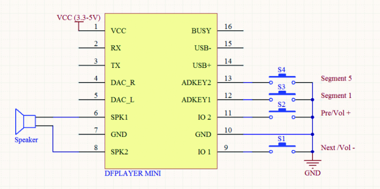
The nativity scene’s audio is obtained thanks to the effective module signed as DFR0299 (you will find it at www.futurashop.it/mini-riproduttore-mp3-montato-9145-dfr0299); it may be controlled by means of the serial interface; in our circuit it uses the microcontroller’s serial hardware interface, the same that is used in order to load the sketch on the microcontroller; this does not represent a problem, however, since the ATmega’s RX and TX lines are used for one function at a time: that is to say, once the microcontroller has been programmed, the sketch uses them in order to manage the module. In the diagram, you may find the DFR0299 represented with the U3 sign; it is capable of directly reproducing the MP3 and WAV files memorized on a SD-Card (having a maximum capacity of 32 GB, as long as it is a FAT16 or FAT32 formatted one) inserted into the dedicated slot.

The peculiarity of this module is that it has been designed and created for the Arduino world: even here the advantage of having an Arduino architecture on our board is obviously an advantage; as for the module’s management, clearly a specific library has been developed (it may be downloaded from our website, www.elettronicain.it, along with the other project files) and it has been included in our sketch; it allows to decide which file to reproduce, how to set the volume, and so on.
The module contains a MP3 decoder and a controller, capable of accessing the data contained in the SD-Card, via SPI: as the data stream is gradually read, the decoder converts it in audio format, that is then amplified by a small integrated amplifier, a mono one having a 3-watt bridge output (that is more than enough power to drive a loudspeaker capable of making its voice heard in the environment). If more power is required, please use the audio output (SPK + and –) in order to drive a power amplifier, to which to apply a cabinet.
All of the functions of the U3 module are managed via serial interface, by means of specific instructions given by the microcontroller: those concerning the volume are generated by reading the ATmega’s ADC, when it samples the voltage on the R6 trimmer’s pointer. We also considered the usage, among the reproduction management commands (Play, Stop, Pause, FWD ecc.) only of the Play/Stop one, that has been implemented by means of the three buttons connected to the microcontroller, via the PD2, PD4 and PD7 lines (all of them are initialized as inputs supplied with an internal pull-up); all of them have the same function, that is to say, the one of enabling/disabling the audio. More precisely, the pressure of one among the P1, P2, P3 buttons (when a track is being played) determines the stop of the same, and a following pressure makes the track previously stopped to start from the beginning.
When the audio track is being played, the LD7 LED is turned on by the microcontroller’s PB5 line (that during the normal operation is used as an output); the PD0 and PD1 lines, depending on the UART, are coupled to the U3 module by means of resistors, so to avoid that – during the programming (that is to say, when the USB/Serial converter is applied to the board) – interferences might arise between the voltages of the two modules.
The files found on the SD Card must compulsorily have the name in the following format: 001.mp3, 002.mp3, 003.mp3 and 004.mp3. The first file is recalled during the day phase, the second one during the sunset, the third one when the hearths are turned on, regards the flickering lights) and the 004.mp3 file is recalled when the dawn comes. For this reason, you will have to rename the track you wish to be played during the day phase as 001.mp3, the one for the sunset as 002.mp3, the one for the hearths being turned on as 003.mp3, and the one to be recalled when the dawn comes as 004.mp3.
During the passage between a phase and the other, the playback volume will be gradually decreased until the end of the track, while the playback of the following track is started, with a volume gradually increasing (as it happens with the radio or the LPs); this happens for the transition from a phase’s track to the following one, and also for a track being reproduced in loop, it being understood that at the fade-out of a playback a similar one is started.

Well, having said that, we will complete the circuit’s description with the parts we omitted until now, that is to say the power supply, the ATmega 328P’s oscillator and the in-circuit programming: the circuit has to be powered with 12÷14 Vcc (the power required depends on how many users you are going to connect to the outputs…) via the +/- PWR terminal box, whose voltage directly reaches the MOSFET outputs and the connector for NeoPixel devices. The main power supply voltage reaches even the D1 diode’s anode (that has been included in order to protect the rest of the circuit from the reversed polarity risk), and is applied to the U2 voltage regulator’s input, whose task is the one to obtain the 5 stabilized volts used for the operation of the microcontroller, of the side components and of the U3 audio module. The possible USB/Serial converter will be powered by the USB voltage of the computer to which it will be connected.
The capacitors placed on the input power supply are needed in order to filter the pulses that are created on the tracks – as a result of the absorption of the LEDs, when they are turned on, and in general of the loads connected to the MOSFET outputs; this is needed since the pulse of the diodes’ power supply has a high frequency and otherwise the noises (that in the end are voltage drops – even if light ones – that are simultaneous with the single LEDs being turned on) might interfere with the microcontroller’s proper operation. The function of the C3 and C4 capacitors is a similar one.
Let’s get down to the interface for the in-circuit programming, now: it is to be used only if you want to load the bootloader in a “virgin” microcontroller; with regard to that, it must be said that the microcontroller supplied by Futura Elettronica (www.futurashop.it) along with the kit has already been programmed with bootloader and sketch. On the other hand, those who will prefer to get their own ATmega 328P elsewhere, will have as a first thing to load the bootloader, in order to be able to transfer the sketch from Arduino IDE.
The designated connector is the one signed as ICSP: the reset (RST), MISO (the programmer’s data input and U1 microcontroller’s output), MOSI (the programmer’s data output and microcontroller’s data input), SCK (the clock for the serial communication on the SPI, composed of the MISO and the MOSI) lines depend on it, in addition to the ground and the Vcc, that during the programming is supplied by the programmer, so to power the circuit. Let’s remember, in fact, that even when programming the bootloader, the circuit must not be powered by means of the +/- PWR terminal box.
Let’s end with the microcontroller’s oscillator, that is set as internal in the bootloader, and has a clock obtained from quartz X1, in parallel to which we will find the R19 resistor; the C5 and C6 capacitors complete the oscillator, that operates at 16 MHz: a frequency that is more than enough to manage the whole control box’s working cycle.

Practical realisation
Let’s move now onto the subject of the board’s construction, that requires the preparation (or the purchase, since all the materials are available at Futura Elettronica) of a double-sided printed circuit board, whose tracks can be downloaded from our website, along with the other project files. Once the stripboard has been engraved and pierced, and the leads have been created (that is to say, the interconnections between pads that are common to the two sides) it is possible to mount the components, starting with the ones having the lowest profile (resistors and D1 Diode), and going on with the microcontroller’s socket, the 6-poles pin-strip with 90° terminals for the (optional) USB/Serial converter, the trimmers, the PCB buttons and the LEDs (to be orientated as shown on the assembling plane, and taking into account that the cathode is the electrode that has been placed on the container’s smoothed side). Please insert and weld the two female 8-pole pin-strips now, so to mount the audio module, the pin-strip for the ICSP (4 poles), the eight terminal boxes and the 7805 regulator, that must be kept upright, with the side having the writings pointed towards the microcontroller’s socket. Now the six MOSFETs must be mounted: each one of them has to be inserted in the corresponding hole in the printed circuit board, after having bent the terminals with a right angle and having put it on (with the side having the writings facing upwards) a “U” heat dissipator of the ML26 kind (thermal resistance: 22° C/W).
Once the weldings have been completed and you have verified that each component has been correctly mounted, and in the expected direction, please insert the DFR0299 module in its pin-strips (by orientating it so that the SD-carrier is pointed towards the outside of the circuit) and the microcontroller, whose reference notch must be pointed towards the integrated U2 regulator.
A micro SD card having the desired capacity must be inserted in the DFR0299, with the chosen audio files already loaded (please do it on a computer); what we claimed a few paragraphs above is valid for them as well. Please remember that – for obvious reasons – the duration of each one of them must not exceed the one that has been set for the phase it has to go with, thus, as an example, the theme being played for the day phase must not last more than the duration set for the day. It is not a problem if the file lasts less, since – it being the case – the file is cyclically reproduced until the end of the time set for the corresponding phase, and therefore faded out in time.
Please remember that the tracks must preferably be placed in the micro sd’s root, but anyway the module is capable of looking into the folders, it being understood that the reproduction order provided for our board would no longer be guaranteed.

At this stage, the control box may require the programming or not, depending on how you created it: if you have acquired a “virgin” microcontroller you will have (by means of the ATMEL programmer or of an Arduino board that has been set as a programmer: that’s the stand-alone programming technique) to load the bootloader by using, for the purpose, the ICSP connection. Once this has been carried out, by removing the programmer and by mounting the USB/Serial interface module in the U4 connector (it is the FT782M, a module that is available at Futura Elettronica, www.futurashop.it, and that is based on FTDI’s integrated circuit, FT232RL), the latter’s USB socket has to be connected to the one of the PC on which the Arduino IDE has been installed, and then the sketch has to be loaded (the IDE sees our board as if it was an Arduino UNO, since the bootloader loaded into the ATmega 328P is the same).
All of this is not required if you purchased the assembly kit, in which the microcontroller has been provided with all the basic functions programmed (4 outputs managed by 4 trimmers).
Anyway, in order to make our project easily adaptable to the user’s needs, the sketch is given in an open source format, and you will be able to download it, always from our website, along with the project files.
Therefore, even if you purchased the kit and are not satisfied with the basic configuration, and want to try to make some changes, you will have to acquire and mount the USB/Serial converter.
VIDEO
From openstore
Board control lights for the crib
FTDI USB-serial converter- 3,3V e 5V
MINI LOUDSPEAKER – 2W / 8 ohm – Ø 66mm

[…] we decided to design and propose a demoboard for the DFR0299 module we already used in the ‘Presepino’ project; this module will function as a development platform for various application or just to […]
[…] as the one shown here; it is based on the DFR0299 module that you already met when we dealt with the Presepino and the MP3 Demoboard […]