
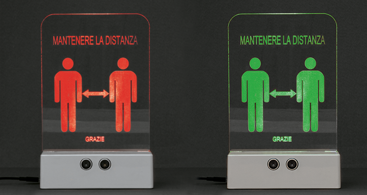
We ensure social distancing with an audible and visual beacon that alerts you when you’re getting too close to a store counter, kiosk or counter.
Since the “restart” after COVID-19 and the various Phase 2, Phase 3 and who knows what else, the expression “social distancing” has entered the common language and also our life habits; but we know that when approaching a counter, a bar or other people, it is not easy to understand if we are respecting the distance that this expression implies, if we don’t have references. In a simple but effective way, the distance in the queues has been marked with adhesive tapes or various signs on the ground, but we who are electronic know that something more can be done, such as the Distance Alert proposed in these pages. The device, which we have called Distance Alert, consists of an obstacle detector capable of providing a small microcontroller board with a signal proportional to the distance of the people in front of it, as well as in a plexiglass display traversed by the light of a Neopixel strip that illuminates across it in red if the distance is less than prescribed and in green if it is at least the minimum required.
But let’s get to the heart of the device explaining its hardware and firmware.
Our Project
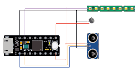
The circuit at the base of the device is essential and is based on a tiny Arduino-compatible board called µchip (code UCHIPWSH), which reads the distance signal provided by a tiny (measuring just 45.5×20.5×15.3 mm) SONAR module labelled MISDIST04 (marketed by Open Electronics – www. open-electronics org), processes it and based on the result composes a colour combination in a data string that is sent to the NeoPixel strip placed at the base of a plexiglass plate, which is responsible for the processing of the data, processes it and, based on the result, composes a colour combination in a data string that is sent to the NeoPixel strip placed at the base of a plexiglass plate, which is entrusted with the task of display. If the signal on the distance indicates an insufficient space, it also operates a buzzer so that it emits an acoustic alarm, while the NeoPixel LEDs produce a red light. Otherwise, where the distance is considered sufficiently high, the buzzer remains at rest and the RGB LED strip emits a green light. The buzzer is a passive type (so a simple piezoelectric board) and is caused to sound by the Arduino board through the generation of a rectangular signal at a frequency determined in the firmware, sent to the pin where it is connected (pin 1).
Note that in reality there is a third threshold that makes the strip’s RGB led turn yellow.
To better understand the operation of the circuit we can explain how the sensor element works, that is the small SONAR, which is interfaced to the µchip board through two lines, a positive and negative 5V power supply that are taken from Vext (pin 16) and GND (8).
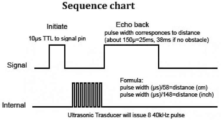
Fig.1
Supplying a positive TTL pulse of 10 µs duration to the Trig input pin, the sensor generates a string of ultrasonic pulses (eight, to be exact) at a frequency of 40 kHz, which are sent, through the transmitting piezo capsule, towards the obstacle; the receiving capsule detects the echo (i.e. the reflection of the obstacle in front of it, as long as it is at an angle of ÷15° with respect to the perpendicular to the printed circuit board) and the electric signal it produces is amplified and compared with the transmitted one in order to obtain the distance information that will be provided to the Echo output pin of the module, in the form of a voltage pulse lasting between 150 µs and 25 ms, proportional to the distance of the obstacle. To be exact, the measurement range is between 2 cm (which corresponds to the shortest output pulse, 150 µs) and 4.5 m (which produces the longest pulse, 25 ms).
If no obstacle is detected within 4.5 m, the module produces a pulse of about 38 ms duration.
The distance in cm (d) can be inferred based on the length of the pulse sent to the Echo pin (t) using the formula:
d = t /58
where the duration of the pulse is expressed in microseconds. As an example, if the Echo returns a pulse 0.58 seconds long (580 µs) it means that the distance detected by the sensor is 10 cm.
It is understood that the 38 millisecond pulse is intended as an out-of-range measurement.
The graph in Fig. 1 gives a clearer idea of how the ultrasonic module works, i.e. how it is triggered by the microcontroller on the Trigger pin (pulse called Initiate in the Signal graph) and when it generates the ultrasonic burst (pulses in the Internal trace) i.e. following the return to logical zero of the Trigger.
How it works
Once this is established, let’s see how the microcontroller inside the µchip board interacts with the ultrasound module: the firmware periodically generates (every half a second) a high-level pulse emitted by pin 10, which drives the Trig pin of the ultrasound module, lasting 10 microseconds; then it “listens” to the Echo pulse provided by SONAR on the homonymous line and acquires it through its I/O line 9. With a timer it counts the duration of this pulse and using the formula already shown, it calculates the distance.
At this point, if the distance is greater than or equal to the threshold (120 cm), it prepares the string directed to the NeoPixel strip with the data for the setting of the green colour and generates it on I/O 7, directed to the DIN of the strip; if it is less than the second threshold (1 meter), it still prepares a string but containing the data to set the ignition of red LEDs, sends it to the usual pin 7 and immediately after that generates the acoustic note by sending it to the piezo buzzer through pin 1. There is a display corresponding to an intermediate distance, between the minimum and maximum threshold, that is when the person is detected at less than 120 cm but more than one meter away: in this case, the microcontroller emits a command string that makes the LEDs turn red.
Remember that the command protocol of the Neopixel system involves sending groups of three bytes in a string of 24 bits, each of which contains the lighting status of each base colour (first the eight bits of green, then those of red and finally those of green).
Fig.2
The firmware
Let’s take a look at the sketch that governs the operation of the device, premising that it is very simplified by virtue of the availability and use of a library for each of the components used in the hardware; then the firmware starts with the inclusion of the libraries:
#include <HCSR04.h>
#include <uChipPowerManagement.h>
#include <Adafruit_NeoPixel.h>
the first of which converts the duration of the pulses of the ultrasonic radar in distance and passes the latter as a variable. The second concerns the power management of the Arduino µchip board and the last is the inevitable library for the management of the NeoPixel strip.
Then we move on to the definition of the assigned pins, which are 1 for the buzzer, 7 for neoPixel data, 9 to read the Echo of the SONAR and get the distance, as well as 10 to control (so it is set as output) the Trig of the SONAR.
Listing 1
#include <HCSR04.h>
#include <uChipPowerManagement.h>
#include <Adafruit_NeoPixel.h>

#define PIN_BUZZER 1
#define PIN        7 // On Trinket or Gemma, suggest changing this to 1

#define NUMPIXELS 8 // Popular NeoPixel ring size

UltraSonicDistanceSensor distanceSensor(10, 9);  // Initialize sensor that uses digital pins 13 and 12.
Adafruit_NeoPixel pixels(NUMPIXELS, PIN, NEO_GRB + NEO_KHZ800);

#define SPACE_MIN 100

uint32_t space;

void setup () {
  // Disabling the boost since the variable was initialized so.
  uChipEnableBoost(UCHIP_BOOST_DISABLED);
  // Setting the external voltage to VUSB
  // The HC-SR04 requires voltage higher than 3.6V
  // and beeps are stronger! :)
  uChipSetVextValue(VEXT_USB);
  pixels.begin(); // INITIALIZE NeoPixel strip object (REQUIRED)


  // Setting up the LED port
  pinMode(LED_BUILTIN, OUTPUT);
  SerialUSB.begin(115200);
  pinMode(PIN_BUZZER, OUTPUT);
  analogWrite(PIN_BUZZER, 0);
  pixels.clear(); // Set all pixel colors to ‘off’

}

void loop () {
    // Every 500 miliseconds, do a measurement using the sensor and print the distance in centimeters.
    space=distanceSensor.measureDistanceCm();
    SerialUSB.println(space);
    delay(500);


    if (space > SPACE_MIN+130) {
        digitalWrite(LED_BUILTIN, LOW);
        SerialUSB.println(“ALL OK”);
        analogWrite(PIN_BUZZER, 0);
        for(int i=0; i<NUMPIXELS; i++) { // For each pixel...
          pixels.setPixelColor(i, pixels.Color(0, 150, 0));
          pixels.show();   // Send the updated pixel colors to the hardware.
        }
    }

    if ((space < SPACE_MIN+20) and (space > SPACE_MIN+10)) {
        digitalWrite(LED_BUILTIN, LOW);
        SerialUSB.println(“PREALARM”);
        analogWrite(PIN_BUZZER, 0);
        for(int i=0; i<NUMPIXELS; i++) { // For each pixel...
          pixels.setPixelColor(i, pixels.Color(255-space, 150, 0));
          pixels.show();   // Send the updated pixel colors to the hardware.
        }
    }

    if (space < SPACE_MIN) {// Turn off buzzer
      digitalWrite(LED_BUILTIN, HIGH);
      SerialUSB.println(“ALARM”);
      analogWrite(PIN_BUZZER, 125);
      for(int i=0; i<NUMPIXELS; i++) { // For each pixel...
        pixels.setPixelColor(i, pixels.Color(255, 0, 0));
        pixels.show();   // Send the updated pixel colors to the hardware.
      }
    }
}
We then move on to the definition of the constant that establishes the reference threshold distance equal to 1 meter:
define SPACE_MIN 100
After the setup, we enter the loop, which involves the sequential execution of an if-else structure in which cyclically (every 500 ms) the ultrasonic sensor is stimulated to make the measurement and provide the result; through the library HCSR04.h the length of the Echo pulse is interpreted and at this point there are two possibilities, with related reactions in case the distance is below the threshold of 1 meter, exceeds it by 20 cm or is greater.
In the first case the affected portion of code is:
if (space < SPACE_MIN) {// Turn off buzzer
digitalWrite(LED_BUILTIN, HIGH);
SerialUSB.println(“ALARM”);
analogWrite(PIN_BUZZER, 125);
for(int i=0; i<NUMPIXELS; i++) { // For each pixel…
pixels.setPixelColor(i, pixels.Color(255, 0, 0));
which basically states that if the distance is less than SPACE_MIN and therefore less than 1 meter, the NeoPixel LEDs turn pure red (in fact the RGB combination is 255, 0, 0) and the buzzer sounds.
If the measured distance is greater than SPACE_MIN but not enough, then the following piece of code comes into play:
if ((space<SPACE_MIN+20) and (space>SPACE_MIN+10)) {
digitalWrite(LED_BUILTIN, LOW);
SerialUSB.println(“PREALARM”);
analogWrite(PIN_BUZZER, 0);
for(int i=0; i<NUMPIXELS; i++) { // For each pixel…
pixels.setPixelColor(i, pixels.Color(255-space, 150, 0));
Here we dictate that if the distance is less than 1 meter and 20 centimetres, the NeoPixel LEDs must light up yellow (the combination of colours R, G, B is 255-space, 150, 0) but of a shade that becomes more orange as the distance approaches the meter (minimum) and more tending to light yellow as the distance to which the detected person is located approaches the meter and 20.

Finally, if the distance is at least 1.2 meters, the third structure is involved:
digitalWrite(LED_BUILTIN, LOW);
SerialUSB.println(“ALL OK”);
analogWrite(PIN_BUZZER, 0);
for(int i=0; i<NUMPIXELS; i++) { // For each pixel…
pixels.setPixelColor(i, pixels.Color(0, 150, 0));
where the firmware, in the absence of one of the two previous conditions (else) turns on only the green sections of the LEDs at brightness 150, indicating that the required “social distancing” has been obtained, i.e. indicating to the observer that he is ok where he stopped.
If you want, you can redefine colours by intervening on the relative portions of the code and remembering that 255 corresponds, for each base colour, to maximum brightness and 0 to off, and that the order of the colours is R, G, B (red, green, blue).
If you are not interested in the variation of the yellow tone, you can modify the instruction:
pixels.setPixelColor(i, pixels.Color(255-space, 150, 0));
by removing 255-space, 150, 0 and writing 255, 150, 0 in parentheses.
Conclusions
The proposed project is a marker that will help you, more than any gesture or word, to keep people waiting at a distance; you can customize it to your taste starting from our concept.
From Open Store
uChip: Arduino Zero compatible in a narrow DIP-16 package (headers already soldered)
Ultrasonic range finder 2-450 cm
NEOPIXEL STICK WITH 8 LED RGB WS2812 AND DRIVER INTEGRATED
