Here comes the third post regarding our amazing OpenWheels: the Segway inspired open source and DIY two-wheels vehicle.
For those who stumble upon this post for the first time, please check the launch here and the whole list here: http://www.open-electronics.org/tag/openwheels/
With this post we get more into the specifics of Openwheels and we’ll talk extensively about the electronics we adopted. The first thing we faced was the choice of the core system to be adopted: being an open source project, the Arduino board looked like the most appropriate choice.
The first Openwheels board we made was made by an Arduino, a breadboard and many connections: although very precarious it allowed us to make our first experiences.

The first issue that we faced was the implementation of the inertial module (IMU) because it is the focal point of the system stabilization. As often, in these cases, all starts by selecting and testing the individual components. The IMU module essentially has the function of detecting OpenWheels inclination respect the (transverse) wheels axis, and the speed with which OpenWheels is leaning forward or backward (basically the speed of rotation of the axis of the wheels). The first component taken into consideration was the MMA7260QT accelerometer provided in a breakout from Pololu and therefore easily interfaced with the Arduino.
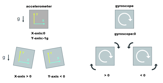
The measurement of terrestrial acceleration compared to the two axes (vertical and horizontal) is able to provide the measurement of the angle of inclination of OpenWheels respect to the vertical axis.
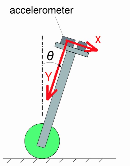
If we define X and Y variables in proportion to the sampling related to the two axes and then appropriately scaled we can obtain the tilt angle by using the following equation: φ = arctg (X / Y).
Despite Arduino provides mathematical functions, including the one we need, to avoid overloading the little CPU, we prefer the use of a simplified equation, that is applicable in view of the fact that the inclination of Openwheels will never exceed 30 °. The simple φ = K * X equation provides the measurement of the angle with an error not exceeding 1% when ranging between -30 ° to +30 °.
Having ruled out vertical axis (Y) this helps to exclude from the measurement all the interferences due to the bumps that would necessarily affect Openwheels while driving. The K constant is determined by considering the sensitivity of the accelerometer and the value provided by Arduino in measuring the analog voltage of the accelerometer using the internal ADC module.
If we define Arduino’s ADC reference voltage Vref [mV] and with sensitivity the sensitivity of the accelerometer [mV / g] the value of K is determined by: K = 360 * Vref / (sensitivity * 2 * PI * 1024).
The value of 1024 is due to the fact that the ADC works in 10bit providing a numeric value between 0 and 1024.
This first measurement of the angle via the accelerometer, that can be used to find the inclination of a tablet or a smartphone, however, is not really unusable for our context. One reason lies in the high amount of noise that affects the voltage generated by the accelerometer and another issue is the unavoidable vibrations and jolts to which OpenWheels is subjected: this would be readily measured by the accelerometer and shown in its output as noise pulse.
To measure Openwheels rotation speed, another kind of sensors may help: gyroscopes. This family of components allow to measure the speed of rotation around one or more axes with extreme precision and with a very limited electrical noise. In addition, gyroscopes are immune to external vibrations. However, measuring the speed of rotation you can’t derive the absolute angle of rotation immediately, you can do that only by means of a mathematical operation which is called integral calculus. Unfortunately, the gyro is affected by the presence of an offset on its output that due tp constructive choices does not remain stable over time: this means that to a zero rotation speed is the output can me different from zero. This problem prevents a proper implementation of integral calculus if not for a very short time of operation.

To obtain an accurate measurement of the angle and of the angular velocity, you need to use the best of both the accelerometer and the gyroscope technologies: the accelerometer measurement will be used in the long run to know the absolute inclination and we’ll take advantage of the gyroscope measurements, to identify the instantaneous changes in inclination. The technique implemented consists in deploying an additional filter to process the accelerometer measurement by a low pass filter and then later merged with the integral of the reading of the gyroscope after being filtered with a high pass filter.

The complementary filter will be implemented digitally through mathematical processing of the samples from the accelerometer and gyroscope. Because of its simplicity it basically sufficient to determine the cutoff frequencies of both the low-pass and high-pass filters: the value is determined experimentally by analyzing the graph of data acquisition. Indeed, thanks to the telemetry system implemented on the board, it will be possible to view all the operating parameters.

In the final version of the machine, we choose MMA7361L accelerometer. For the gyroscope, the choice fell on the LPY503AL model. The electronic board for Openwheels accepts both the installation of these two breakout and the direct bonding of the two chips: this solution allows you to save on the bill of materials but welding in SMD is achievable only by very experienced staff provided with the right equipment.
Let’s now describe the method used to measure the angle of the handlebar. This value will be used to implement steering. Thanks to a clever mechanical work made by our Gabriele Draghetta the entire handlebar is free to tilt around a pivot fixed to the platform on which a potentiometer is keyed. The potentiometer used as a voltage divider gives measures proportional to the inclination angle of the handlebar that are easily read by the ADC module.
OpenWheels’ board is equipped with a telemetry system based on a Xbee module. These modules implement everything you need to establish a remote transmission making a serial transmission completely transparent, as if it was made by a cable. For our application two low power, 1mW Chip Antenna, modules are sufficient: one will be on the board and the other one will be interfaced to the PC for the display of telemetry. The programming of the two modules will be described when we will take care of the software part.

One discarded other commercial solutions that would have increased the final costs, we opted to create our own engine drivers. The driver had to be fed with 24V and capable of handling more than 10Ampere (easily absorbed by each engine at full power). It also was necessary to take into account the surge current peaks due acceleration and speed adjustments.
Some considerations about the mode of operation of the driver were also made. When in vertical position, the motors may undergo sudden changes of direction which made us exclude the operation mode based on PWM and direction (sign-magnitude mode) that you normally use on the various Motor Shields for Arduino. Using this mode of control, when OpenWheels is stationary in the vertical position the PWM signal for controlling the power of the engines has a very low duty-cycle, while the direction signal changes state often and this is a very stressful situation for the driver and generating short-lived pulse signals, always involves electrical issues. To overcome these drawbacks, our driver works in the mode called locked-antiphase that, although not very used, it’s optimal in applications like this.
During operation, the Q1 and Q4 MOSFETs pair are ON alternately to the Q2 and Q3 pair, it is like we feed the maximum voltage first in one direction and then the in the other. If the load consisted of a light bulb, it would always be running on full power regardless of the duty cycle with which we command the two pair of MOSFETs. An electric motor instead is a load (electrically wise) composed of a resistive and an inductive component (RL series) and then also if you energize instantly in one direction its current takes time to increase according to the time constant determined by the L / R ratio; the trend of the voltages and currents is shown in figure-

If the duty cycle is 50% of the engine will be alternately fed with + Vcc and -Vcc with an average value of zero, while the current trend will assume a triangular wave (also with zero mean value), ie: the motor will not rotate in any way. If the duty cycle is different from zero, the average voltage at its ends will be different from zero as well as for the current and the motor will be powered.

The speed of rotation is dependent on the supply voltage, which in turn will be directly proportional to the duty cycle with which we command the driver.
As you can see the MOSFET command is not impulsive and in the case of a still motor is simply a square wave.
To implement a driver with these characteristics, we used a specific integrated circuit for the control of power MOSFETs that is named IRS2184 to which we combined four automotive MOSFETs called AUIRF2804.
The chosen MOSFET support voltages up to 40volt with currents over 200 ampere, more than sufficient for our purpose. Do not be fooled by the maximum current limit manageable because the operational limits will be set by the power dissipation in the MOSFET, due to its resistance and conduction losses during the switching phase. The power dissipated during the run (ON) is determined with the equation P = RDS (on)· I2 and thus it strongly depends on the value of the current but also on the internal resistance. This is typically 1.5 Megaohm . The IC IRS2184 is specifically designed to handle the two MOSFETs from each of the H-bridge branch, introducing also a short delay when switching between the MOSFETs . The management of the MOSFET above takes place in floating mode with a technique called bootstrap.This particular technique allows the use of both the N-channel MOSFET. The upper MOSFET’s gate is handled with a higher voltage than the supply, thanks to a charge pump system that goes through a diode and a capacitor. This is a big advantage because it allows you to choose the best performing MOSFETs and less expensive but on the other hand makes it impossible to use a duty cycle of less than 5% and greater than 95%, as it would prevent proper charging of the bootstrap capacitor. This driver configuration is perfect for control in lockedantiphase mode.

With two IRS2184 IC and four MOSFETs a full H-bridge is made that is suitable for the management of an engine in the four quadrants; a driver is directly controlled by the PWM signal while the other is driven with the opposite signal. The two transistors are placed on the inputs of the driver precisely serve to obtain the inversion of the PWM input signal, as required in locked antiphase mode. With only two PWM signals we manage both the drivers and consequently the two engines, a third signal indicated by shutdown is used to disable the driver when OpenWheels is in standby. Indeed, using the locked antiphase mode, even with still engines there is a minimum current consumption, and in addition there is the need to leave powered the entire control section while, for example, you manually move OpenWheels. With the driver in shutdown all the MOSFETs are in OFF status and the wheels can rotate freely allowing you to simply drag OpenWheels. Peculiar attention has been paid to the proper choice of PWM signal frequency used to control the drivers, in consideration of multiple factors.. As described above, in the locked antiphase mode, engine current has a certain oscillation (it varies between a maximum value and a minimum value linearly) that is greater as lower the frequency of the PWM and as lower the inductance of the motor. To avoid an excessive current ripple it is necessary that the PWM frequency is high enough compared with the time constant of the electric motor: for experimental purposes is good to respect the following equation: fPWM>10 · Rm/ Lm. Operating a motor with a PWM signal also introduces vibrations on the internal windings that result in an annoying audible hiss, so if you’re working at audio frequencies. Both of these considerations led us to choose a PWM frequency that is more than 10-12KHz, the limit beyond which the human auditory sensitivity decreases rapidly. But we cannot rise too much the PWM frequency due to the inevitable losses that are induced within the magnetic core of the engine, when affected by strongly variable magnetic fields. The same driver presents specific losses due to the switching phase, during which the MOSFET pass from the OFF state to the ON state and vice versa.
The four IRS2184 IC require a power supply of 12volt that derives directly from the 24volt main battery voltage via a step-down switching power supply based on the LM2576. The high efficiency of this type of power supplies saves us the need for a massive heat sink and limits the current consumption of the power supply batteries. This chip runs at a fixed frequency of 50KHz and with the values we have chosen the output ripple value is less than 4mVrms. From this first regulated voltage, via a LDO stabilizer, we derive the 5v to power the logic and subsequently through a second LDO regulator we derive the 3.3 volts for the power supply of the sensors and the ZigBee module. 5v is used to feed an LED used as an indication of a proper power supply. To complete the hardware we inserted a voltage divider that is necessary to measure the voltage of the battery power supply plus a current sensor based on the ACS758 IC. The latter uses Hall effect to measure the current without drop voltages, as per the shunt technique. There’ll be an output voltage that is proportional to the current – in accordance with the internal scale of the IC – allowing up to 50 ampere.
Indication of the current drawn will be successively monitored and made available for consumption analysis but will also be used as a security system, allowing to Switch off driver power as soon as it detects an abnormal absorption current. Since this system can have some delays you find two fuses on the diagram located on the power of each driver that are ready to intervene in case of brutal short circuits. A third fuse is to protect the control section.
The final board is based on the Arduino chip in SMD version: the ATMEL 328AU1217 integrated fully exploited as regards the hardware but also in software. We provided the standard Arduino board connector for in-circuit programming required to load the bootloader and the programming will be done via the serial port of the chip using a USB-serial converter to connect the PC. It will be like programming an Arduino duemilanove . The Xbee module engages the serial port, so, to avoid conflicts, we provided a small jumper to enable the Xbee module; the jumper will be removed during the programming phase of the Atmel chip. We also added a small soldering jumper that connects DIO3 pin Xbee with the Atmel RESET with the aim, for those who wish to enable wireless programming. This mode is very interesting because it allows you to program the Atmel creating a transparent communication between the PC and the Chip via the Xbee modules, the DIO3 line in this case acts as an automatic reset. This mode, however, implies a specific programming for the two Xbee modules. A special connector allows to connect the steering potentiometer, while a second connector takes the signals to the rod of the handlebar in which few buttons and an LCD display are located. We provided a start button on the handlebar: in case of a fall if you remove your hands from the handlebars this will disable engines. On the handlebar you can also find a serial LCD display that will show all the information indicated by the operation and any error states, will also be used as a monitor for the main operating parameters. OpenWheels can be configured remotely, but those who want to save on Xbee modules for telemetry can use the LCD display and the buttons on the handlebar to set the operating parameters. On the printed board you also find JP3 JP4 used to select the gyroscope range. If shorted, the JP2 jumper is used to enable the programming of the Atmel chip remotely via the XBee module. In fact, the DIO3 output of the XBee module can be programmed to reset the Atmel chip during programming, a function normally carried out by the DTR line of the USB / serial converter. The remote programming is possible only after having properly programmed the two XBee modules responsible for serial communication.

BOM
R1÷R4: 4,7 ohm (0805)
R5, R6: 1 kohm (0805)
R7: 4,7 kohm (0805)
R8, R9: 2,2 kohm (0805)
R10: 47 kohm (0805)
R11, R13÷R16: 4,7 kohm (0805)
R12: 33 kohm (0805)
R17, R18: 1 kohm (0805)
R19: 4,7 kohm (0805)
R20: 33 kohm (0805)
R21: 10 kohm (0805)
R22÷R25: 1 kohm (0805)
R26: 10 kohm (0805)
C1, C2: 10 μF 35 VL (B)
C3÷C5: 100 nF (0805)
C6: 1000 μF 35 VL
C7, C8: 10 μF 25 VL (A)
C9: 1000 μF 35 VL
C10: 100 nF (0805)
C11: 100 μF 35 VL (F)
C12: 220 μF 25 VL (F)
C13: 10 μF 35 VL (B)
C14÷C17: 100 nF (0805)
C18: 10 μF 50 VL (B)
C19, C21÷C23: 100 nF (0805)
C20: 10 μF 35 VL (B)
C24, C27: 1000 μF 35 VL
C25, C26: 10 μF 25 VL (A)
C28: 100 nF (0805)
C29, C30: 10 μF 35 VL (B)
C31: 100 nF (0805)
C32: 10 μF 35 VL (B)
C33, C36: 100 nF ceramico (0805)
C34. C35: 22 pF (0805)
C37: 220 nF (0805)
C38, C40: 10 μF 35 VL (B)
C39, C41: 100 nF (0805)
C42: 3,3 nF (0805)
C43, C47÷C49: 100 nF (0805)
C44: 10 μF 35 VL (B)
C45: 470 nF (0805)
C46: 10 nF (0805)
C50: 3,3 nF (0805)
C51: 10 μF 35 VL (B)
C52: 100 nF (0805)
D1: GF1M
D2÷D6: BAT42W
D7: GF1M
T1, T2: BC817
T3÷T10: AUIRF2804S
Q1: 16 MHz
U1: ACS758LCB-050U-PFF
U2: LM2576HVS-12/NOPB
U3: LM2937IMP-5.0/NOPB
U4÷U7: IRS2184S
U8: ATMEGA328-AU
U9: LPR403 o WRL-10415
U10: MMA7361
U11: XBEE1MWCHIP
U12: TC1262-3.3VDB
L1: 470 μH 850 mA
F1: 1A
F2, F3: 10A
LD1, LD2: LED green(0805)
LD3, LD4: LED red (0805)
Testing
Since a vehicle like openwheels can be dangerous it’s super important to test.
For the moment we will not put the Xbee modules, neither the fuses or the accelerometer and gyroscope; we will only insert the F1 fuse from 1A to feed the control part. If the board is supplied without a bootloader you must load it, the procedure is well documented in this post.
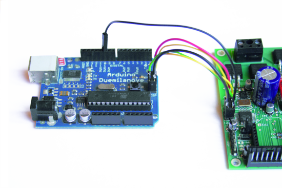
This board is in all respects an Arduino duemilanove compatible and subsequent programming operations will be done via a USB / serial converter based on the FDTI chip. For our operations, we used SparkFun’s USB / serial converter.

A first test at the counter simply provides powering the board via an external 24VDC: would be ideal to have a stabilized power supply with current limiting function. Use a multimeter to check that the power supply voltages on the +5 V and +3.3 V are correct; LED LD2 must be turned on.
At this point you are ready to wire the various electrical components and finally make OpenWheels operating; There will be a bit of electrical work to be done.
A first step is to wire the steering potentiometer, we will use the 4×0,25 four-wire commercial cable, even if we are interested in only three. Solder the three wires to the three terminals of the potentiometer and the corresponding heads will simply pay the appropriate connector according to the following indication: pin 1 of the connector must match the pin toward the left wheel.

It’s definitely the case to check that the electrical connection is optimal by measuring the resistance on the connector that is not yet inserted on the Openwheels board. Also check that the potentiometer is centered: between pin 1 and 2 of the connector should measure a resistance of about 5Kohm (you do not need great precision) as well as between pin 2 and 3.
We now wire the handlebar: to do this we use a 8×0,25 cable and, as done previously, we solder an eight-pole connector on the board side, while on the other side will be wired into the LCD and buttons as shown in figure.

On the handlebar, at reach of your right (or left) thumb you must also install the start button, while the LCD display should be in a central location and easily visible while driving. The buttons for setting parameters can be placed near the display. It is logical to put P1 to the left (decrease) and P2 to the right (increase) while P3could be either at the center or to the right of all buttons.


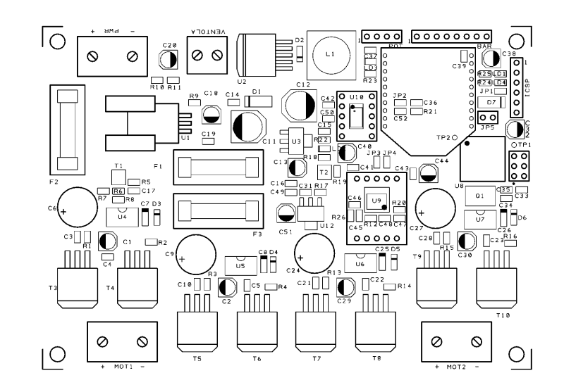
The board features four holes at the four corners that, by using screws and plastic spacers, allow the mounting on the main crossbar, the one located on the same axis of the wheels. Make sure that the board does not touch on the aluminum bar below and creates a shortcut on the copper. The two batteries delimit the insertion of the board and, at the same time, protects it from accidental bumps from below. Particular attention should be paid to the correct orientation of the board to avoid a misreading of the sensors, observe carefully the pictures: the MOT1 connector must be located on the right side of Openwheels.
Electrical connections are simplified thanks to the connectors on the board: the first link is to be realized to power of the batteries; for the moment we take care of the sensor test: we will not link the motors for now. The two batteries must be connected in series, then a wire that connects the positive terminal of one to the negative terminal of the other it’s necessary; let’s take advantage of this link to insert a fuse to protect the batteries from short circuits.
A second wiring shall be made to bring power to the board; we will also put the main switch in series in this connection. There is no definite place in which to put this switch, however, we recommend an easily accessible location that minimizes wires length, to reduce electrical losses on the cables. Since the toggle switch could be inadvertently activated, if you want to completely disable OpenWheels, the best solution is to pull the fuse on the wire that connects the batteries in series. Enter the accelerometer and gyroscope scrupulously observing the direction of insertion. Still without fuses on the power, power up the board and check that the Power LED is correctly lit. At this point you can load the OpenWheelsTestSens sketch that allows you to initialize the LCD and test the sensors.
Open the Arduino Serial Monitor and setup a 115Kbps communication, OpenWheels will send data about the state of the sensors and at the same time will update the LCD display.
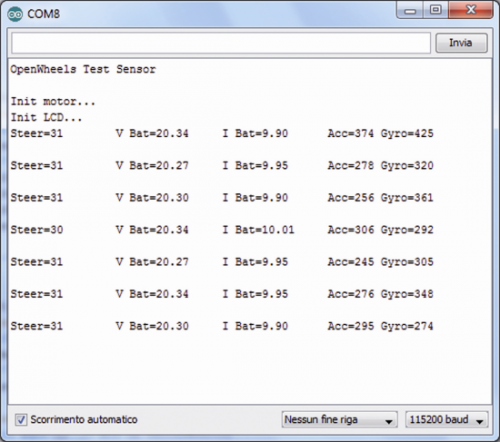
These are unprocessed values provided by the ADC module and Arduino, except for the measurement of voltage and current on the battery. Verify that the value of the voltage on the battery is real; current measurement should be basically zero. A verification of the precision of the current can be done by inserting a small resistive load on the fan connector. The variable related to steering must provide an intermediate value between 0 and 1024, about 512, by tilting the handlebar this value should vary proportionately.

When at rest the accelerometer gives a value of about 1.65 V or about 512 on the display while the gyroscope provides a resting value of 1.3 V or 380 on the display. Both these values vary according to the inclination of the board. Make sure the buttons are working properly, press them and check that the display shows the indication. A first examination of the sensors working status can be performed by tilting the handlebar slightly forward and backward: the reading of the accelerometer remains almost stable in the position reached instead of the gyro varies its indication only during the rotation of the handlebar, returning to the default value when the inclination remains constant. This explains the conditions described in the previous article when we described the selection of the sensors. While the gyroscope provides an indication of the rotating dynamics, the accelerometer provides an absolute indication of the inclination of OpenWheels. Another important point relates with the measure “cleaness”: while the gyroscope provides a very clean measurement, that of the accelerometer is affected by the internal noise of its components and is sensitive to any external vibration. We’ll go deep on these aspects when the telemetry will be implemented and the data captured by the sensors will be available in an appropriate graph.
Now that you’re getting to grips with OpenWheels can test the engines. We need to do it safely then, we should make sure that OpenWheels is off the ground, it would be better to remove the wheels leaving the engine free to rotate. In these early sketches protections are not implemented at the software level so remember to always use the utmost caution. The right motor should be wired on the right connector called MOT1 and consequently the engine on the left should be on connector MOT2; to ensure the correct direction of rotation check the illustration printed on the board. Now it’s necessary to enter the two power fuses, perhaps reducing their value to just 5A. The sketch called OpenWheelsTestMotor allows you to test the engines simply changing the value of the duty cycle that can be set using P + and P- buttons. The value of the duty cycle will be visible on both the serial monitor and the LCD. Holding down a button you can quickly vary the value of the PWM and thus the speed of rotation of the motor. Always pay close attention during this test because it is potentially dangerous.
As you know already, the PStart button on the handlebar, is used to enable the power driver: the motor rotates only with this button pressed. To avoid damaging current spikes, it would be appropriate to press and release this button only when the PWM is set to zero. By pressing the Enter button the value of the PWM is immediately set to zero. You can also follow this procedure before installing the card mechanics, using a small 24VDC motor. As you will see the Start button will be very handy for Openwheels: once powered up, it will be fully operational in stand-by mode with very low absorption. In this mode, all functions are implemented and the display will provide a range of information on the reading of the sensors but the engines will not be operated, thus being able to rotate freely. In this operational mode Openwheels can easily be dragged by pulling on the handlebars.
Ready for some action?

Hi Boris,
I am waiting eagerly to build my own OpenWheels. May I know when the entire code and schematics/boards will be available?
Thanks so much for the efforts!
Dave
http://www.open-electronics.org/tag/openwheels/
où peut ton se procurer le schematic ?
Hi Boris,
I have a few questions regarding the schematics:
– In the post you say that for the final version, the LPY503AL gyro was chosen, but in the BOM, U9 is “LPR403 o WRL-10415”. Is this a mistake? And I understand that the schematic shows only the direct bonding version of the gyro and acc. right?
– I take it that the 2 parts of the driver to control MOT1 & MOT2 are identical, but pin 2 of U5 is connected to a resistor (R8) going to GND, while pin 2 of U7 doesn’t have this resistor. Is it missing?
– What is the use of TP1, TP2 and TP3?
– And lastly, what would be your comment on using the MCU6050 (gyro & acc. combined) in place of the above? It is much cheaper and has better availability.
Thanks!
Kenny
Hello,
I came across the artique and I asked myself the same question, did you have an answer regarding the lpy503al, I have the new card f1169m but I am bib for the moment.
Thank you
Marcel
R1-R4 is 4.7 ohm but R13-R16 is 4.7K. Why different? Is this documentation reliable to build?
Hi Boris,
THanks for all of the great information. Would it be possible for you to send me the circuit diagrams and pcb layouts for the final boards you used, as the images you have on the website are too small to be able to view the component numbers.
Many Thanks
Laurence
Click on the image
Thanks for all. May you share the PCB also?
We are thinking to create OpenWheels in our school in Naples, in a project with our best students.
Not yet, we are working at a new version
Still working on the new board? I am looking forward to it…
I have a question. Anybody with OpenWheels capable of producing usable, high resolution schematics.
A simple request, shouldn’t be that hard.
Oh wait, I see the philosophy. It is an experiment from beginning to end, so we don’t want to make it too easy at any point.
It is disgusting that people get away with this quality of work.
Brian K Mcclung
BKM Engineering
I don’t understand what are you saying…
Have you try to click on the image?
We don’t sell anything about this project… So why we create this post?
To share our experiments….
ahhh this is the schematics…
http://www.open-electronics.org/wp-content/uploads/2014/05/1027_Schema.png
Hi,
I’ve been looking at this some for some time.
I have the electromechanics build up to drive for my inmoov,
but now looking for the electronics for the balancing scooter.
Getting all the electronics components is possible, but I still need the blank PCB
to solder all the components on, it is possible to get the PCB and I prefer
assembled ? This would be easyer and less time consuming ?
Thanks for all the hard work that has been put in to this project
Michel
Thank you for sharing this project and making it open source. However, I cannot find either the PCB design or a complete firmware listing anywhere. Here, I find only bits and pieces of such information. Are there no Eagle/KiCAD/Diptrace PCB and schematic open SOURCE files? Where should we be looking for the complete project open SOURCE files? All we see here is some blog posts with partial information. This is not like any other “open source” project I have ever seen or been involved with. Just saying. Thank you.
Hi Boris. I hope you are well. Your project is quite interesting and I would like to build it. Can you please share the code and the board gerbers if possible. Tx
We are working at a new board