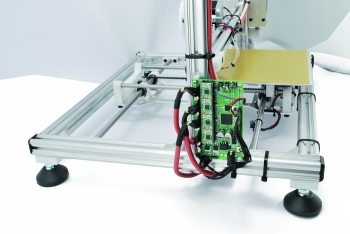
Let’s improve the 3Drag with this new board that allows to control a fan and (thanks to the ATmega2560 processor) add some code and accessory devices such as a display or an SD Card
When we first released our 3D printer, we tried to use some parts that were already available and tested, in full respect of the open source philosophy. In particular, we decided to use the electronic card Sanguinololu. The “open” firmware we chose, the Marlin firmware by Erik van der Zalm, solved the biggest part of the computer interface issues. The Sanguinololu was great, but being innovators by vocation, we looked around testing new developments. The first improvement was about introducing a fan, capable of blowing cool air on the just deposed layers, while the second came from the Sanguinololu weaknesses in managing the heated plate. The first new feature is very useful because it allows you to cool the deposed material more quickly and makes it more viscous than the subsequent deposition, while the latter is for those who want to use the ABS and serves to prevent the deformation of the lower layers the piece.
Unfortunately with the original Sanguinololu card, which indeed sports a dedicated output for controlling a heating plate, we were able to control power heaters of quite limited power that couldn’t keep up with our requirements. In addition, the control outputs of the Sanguinololu (which is the classical RepRap board) are sufficient to check only the four bipolar stepper motors that drive the mechanics, the extruder heater, the heated plate, and two inputs to read the temperature.
Since we were looking for something more, we evaluated two possibilities: to design a board from scratch or try a customizable open source solution. Eventually we found an interesting starting point in an open source project, that of the RAMPS board. Amending and supplementing the RAMPS board schematics, we derived the unit described in this post.
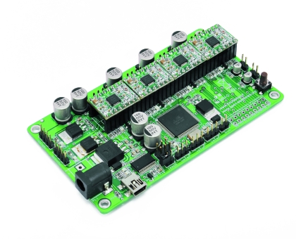
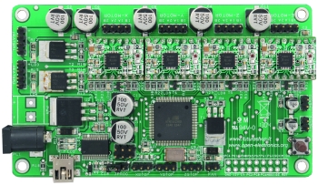
We replaced the original microcontroller with a great Atmel ATmega 2560, that can accommodate more lines of code in the Flash and allows us to implement more features than those of a typical 3D printers control board. We also re-shared the design in open source, in full respect of the open source world rules.
Compared to other solutions available on the market, this solution allows those who know how to program the ATmega with the Arduino IDE to add functions and enhance the functionality by modifying the available source code: you’ll not feel limited by the scarcity of program memory that characterizes the micro (ATmega 644) available on the original Sanguinololu board.
Indeed, the ATmega2560 processor sports 256 KB of program memory with 16 MHz clock. Our board can be programmed directly from the Arduino IDE: a USB connection to connect via a standard miniUSB cable is available, and the same port allows PC control during prints.
Our board allows you to control a cooling fan: this is very useful since both the printing software Repetier host and the slicing software Slic3r include cooling management during extrusion phase: the fan is activated only when necessary, with a speed that is tuned on the characteristics of the printing layers.
The board also sports few LEDs connected to the stepper motors drivers, allowing you to check immediately whether the microcontroller commands are correctly given letting you check the operation status of the system in case of fault. Even MOSFETs that drive the extruder heater and the heated plate are matched with LEDs with the very same function. The same was done for the FT232RL that deals with the USB / serial conversion: it’s equipped with LEDs indicating information exchange with the PC.
Regarding the control of the stepper-motors: the default drivers configuration is 1/16 of a step: by cutting the three thin tracks on the bottom, those connecting two by two the jumpers’ pitches, you can solder the standard pin-strips to operate the manual selection of the steps through 2,54 mm jumpers. This operation can be made for one or more drivers depending on the needs.
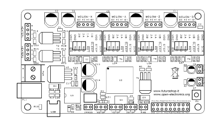
Let’s see the circuit diagram that describes our unit.
The diagram

The circuit may appear small but it is a little complex, given that counts a 100-pin microcontroller, four stepper motors drivers, three MOSFETs allowing us to drive two heaters (one is that heating of the plate and the other one heats the nozzle of the extruder) and a low tension fan, as well as a USB / serial converter to interface the ATmega with the computer and to a power supply stage, which completes the ensemble.
As said the microcontroller is loaded with “Marlin” firmware properly configured to drive the electronics.
The drivers motors are produced on our own and can be found in the scheme as signed U4, U5, U6, U7. Each module is essentially an Allegro A4988, very versatile since it can be set to define both the direction of rotation of the motor shaft and the number of degrees that the rotor must complete after each command: we can decide whether when we provide a pulse, the module will rotate the shaft of 1, 1/2, 1/4, 1/8 or 1/16 of a step at a time, based on the accuracy that you want to get.
Each driver consists of a dual H-bridge managed by an electronic device that allows you to set the direction of rotation of the electromagnetic field and, then, of the stepper-motor shaft. Each time a pulse arrives on pin STEP (the minimum allowable is 1 µs), unless otherwise set, outputs 1A, 1B, 2A and 2B provide the pulses for controlling the displacement of the rotor unless the inputs MS1, MS2, MS3 are set differently.
Notice that the /STEP line of each controller is connected to an NPN transistor, which serves as a current amplifier to drive a LED, which will pulsate similarly to the corresponding command line of the microcontroller (PA4 for U4, PF6 for U5, PF0 for U6 and PL3 for U7) so that we monitor what happens. Thus, in the case that an engine does not rotate despite its related LED pulses, it means that the problem is within the driver or the motor, or in the wiring. It is understood that since the LED pulses at the same frequency of the control pulses, we can see it flashing only when the corresponding motor will run at very low speed, since already at 25 Hz, the human eye sees the diode always illuminated.
Let’s talk about the MOSFET driver used to power the heaters and the fan: they are all BUK6215-75C, manufactured by NXP, with N-enhancement mode channel, capable of a drain current that reaches 57A and capable to bear with a Vds in lock state, of 75 V; their very low Rdson (15 milliohms max with a drain current of 15A) is used to minimize the power dissipation and therefore being able to solder them directly to the PCB track (which acts as a heat sink). The case is a SOT428, for surface mount, and allows to do this.
In our case the MOSFETs are used with small currents, because we are in the order of 2 to 2.5 A for the heater extruder (which must be connected to HEATER1) and 5 to 6 A for the heated plate (to be connected to HEATER2), which is why there is no need to equip them with the heat sink and they cool just thanks to the dissipative effect of the slopes where the foil collector is welded.
Each of the heaters related outputs is provided with a pulsating LED associated with the 4 Hz PWM signal, allowing to visually check the state of operation, the PWM of the cooling fan is instead at a higher frequency and the corresponding LED will seem always switched on when the fan is on, regardless of the speed of rotation.
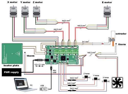
Continuing with the analysis of the I / O of the microcontroller, PE5, PJ1 and PD3, serve to read the status of the end-of-run switches on the three axes; for the accuracy, PE5 and PJ1 respectively detect the end of run of the plate (horizontally) forward/backward and sideways. Instead PD3 detects the end of run of the extruder mover. All lines are equipped with internal pull-up, enabled by the firmware.
End of run switches, when properly placed, are turned on when the plate or the print head support arrives at the end of the run: in our case those are mounted on the chassis.
Using a end-of-run switch, we can connect with the contact between S and – (ground) on the understanding that it will be necessary to instruct the firmware to both read the low logic state, and set the internal pull-up on pins 7, 64 and 46 of the microcontroller.
Well, let’s now check the PC communication section, which belongs to the lines PE0, PE1 and RST of the microcontroller: the first two are assigned to the internal UART, which communicates with the USB / serial converter U3. The latter is an FT232RL from FTDI, and contains the logic that is necessary to transform the data from the TTL serial format to USB, sorting incoming data from TXD and RXD on DP and DM pins. The chip is powered directly from the USB’s 5 volt.
LEDs dubbed LD6 and LD5 locally indicate the activity of the transmission lines and data retrieval.
Notice that the integrated circuit is provided with pins for some of the control signals of the RS232 standard, of which we use the DTR (Data Terminal Ready) to start the bootloader when you need to load the firmware into the microcontroller.
Continuing the circuit analysis we can look to PK5 and PK6 lines, thanks to which the micro reads from the temperature sensors from the heaters. These sensors are 100 kohm/25 °C NTC thermistors to be connected to the THERM1 and THERM2 contacts. More in details, THERM1 is connected to the extruder sensor, while NTC should be connected to THERM2 that detects the temperature reached from the potentially heated plate.
The two probes are fundamental to stabilize the extruder temperature: in fact they allow the microcontroller to adjust the current supplied to the resistor that heats the nozzle so as to keep the temperature set.
Without this feedback we couldn’t stabilize the temperature: even admitting to work with a constant current and supposing that this corresponds to a certain temperature, environmental and operational changes could alter the temperature at which the plastic material is brought to extrude, with obvious deposition and printing problems.
As said, the thermistors used in our machine are 100 kohm / 25 ° C from NTC.
BOM
R1: 10 kohm (0805)
R2: 10 kohm (0805)
R3: 330 ohm (0805)
R4: 10 ohm (0805)
R5: 100 kohm (0805)
R6: 1,8 kohm (0805)
R7: 4,7 kohm (0805)
R8: 4,7 kohm (0805)
R9: 4,7 kohm (0805)
R10: 10 ohm (0805)
R11: 100 kohm (0805)
R12: 1,8 kohm (0805)
R13: 10 ohm (0805)
R14: 100 kohm (0805)
R15: 1,8 kohm (0805)
R16: 470 ohm (0805)
R17: 470 ohm (0805)
R18: 10 ohm (0805)
R19: 10 ohm (0805)
R20: 330 ohm (0805)
R21: 330 ohm (0805)
R22: 330 ohm (0805)
R23: 330 ohm (0805)
R24: 10 kohm (0805)
R25: 10 kohm (0805)
R26: 10 kohm (0805)
R27: 10 kohm (0805)
R28: 100 kohm (0805)
R29: 100 kohm (0805)
R30: 100 kohm (0805)
R31: 100 kohm (0805)
R32: 4,7 kohm (0805)
R33: 4,7 kohm (0805)
R34: 4,7 kohm (0805)
R35: 4,7 kohm (0805)
R36: 10 kohm (0805)
R37: 10 kohm (0805)
C1: 100 nF (0805)
C2: 100 µF 25 VL (E)
C3: 100 nF (0805)
C4: 100 µF 25 VL (E)
C5: 100 µF 25 VL (E)
C6: 100 µF 25 VL (E)
C7: 10 µF 35 VL (B)
C8: 10 µF 35 VL (B)
C9: 22 pF (0805)
C10: 22 pF (0805)
C11: 100 µF 25 VL (E)
C12: 100 nF (0805)
C13: 100 µF 25 VL (E)
C14: 100 µF 25 VL (E)
C15: 100 nF (0805)
C16: 100 nF (0805)
C17: 100 nF (0805)
C18: 100 nF (0805)
D1: GF1M
D2: BAT42W
D3: MBRA140TRPBF
T1: BUK6215-75C
T2: BUK6215-75C
T3: BUK6215-75C
T4: BC817
T5: BC817
T6: BC817
T7: BC817
U1: ATMEGA2560-16AU
U2: MC7805ABD2T (D2PAK) > cod. RS 516-5988P
U3: FT232RL
U4: Driver
U5: Driver
U6: Driver
U7: Driver
LD1: LED (0805)
LD2: LED (0805)
LD3: LED (0805)
LD4: LED (0805)
LD5: LED (0805)
LD6: LED (0805)
LD7: LED (0805)
LD9: LED (0805)
LD10: LED (0805)
P1: Microswitch
Q1: 16 MHz (C7S)
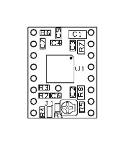
The stepper motor driver module
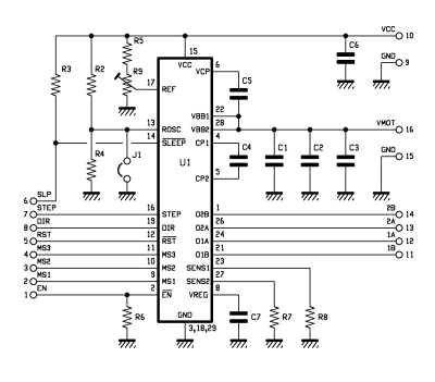
The control of the stepper motors has been entrusted to four modules based on the Allegro’s A4988 integrated circuit which sports a dual H-bridge driver governed by a logic that controls the motor ignition and allows the motor to make shorter steps. As an example for each control pulse sent to STEP (the pin that receives the motor drive pulses) the stepper-motor can take an entire step or fractions ranging from 1/2 to 1/16, depending on the combination logic on MS1, MS2, MS3.
The direction of the movement resulting from each pulse received on STEP depends on the logic level applied to DIR (the logic 1 implements anticlockwise rotation, 0 makes it clockwise). Each bridge can deliver a current of 2 A, while the module is fed continuously with voltages up to 35 V; a small trimmer on the base and connected to the A4983’s REF pin (17), allows you to adjust the bridges output current.
The module allows you to disable the H bridge while still being fed: just bring the EN line to a high logic level. For normal operation, this contact must be set to zero; note that EN can not be managed, as the module incorporates a pull-down resistor (R6) that in the absence of control voltage supplied from outside keeps it enabled.
The SLEEP line deactivates U1, without un-powering the module; it is kept at a high logic level by the pull-up resistor R3: in the absence of an external control the module is always active. By placing SLP to logic zero, U1 goes into sleep mode, or in standby, absorbing a few tens of microamps, in this mode does not drive the H-bridge and does not respond to any commands.
Operation of the bridges is governed by a PWM signal generated by a circuit controlled by a one-shot timer, whose off pulse duration determines the off time of each MOSFET. Depending on the voltage applied to Rosc three modes of operation are possible:
– Vdd = off time is permanently set to 30 ms and the decay mode is Mixed except when you opt for 1/1 step mode
-mass (J1 closed) = off-time is 30 microseconds, while the decay mode is Mixed for both growing and declining currents, except in 1/1 step mode;
– intermediate voltage = off time is defined (in microseconds) from this formula toff ≈ ROSC / 825.
Such rules are related to engine command pulses that, if the output current reaches the limit value fixed by the trimmer applied to Vref (Imax),have an envelope that has a rapid rise time and then a Mixed decay. When this occurs, the MOSFET of the bridge makes the output current decrease (for the 32.5% of the toff time) quickly at the start and then slower.
The current delivered by each bridge can be easily regulated and limited by the application of a control potential to A4988’s pin 17 (by means of R9). The maximum current supplied by the driver (Imax) is defined by the formula:
Imax = Vref / 8xRs
where Vref is the voltage applied to pin 17 of the integrated circuit and Rs is the value of the resistor connected to the Sense pin (SENS1 for a bridge and SENS2 for the other). To have the same current on both bridges R7 should be equal to R8.
How to enable the 3Drag controlle in Marlin Firmware
The latest Marlin version already incorporates the 3Drag controller; the changes needed to make Marlin usable with the 3Drag are the following
| Old instruction | New Instruction |
| #define MOTHERBOARD 7 | #define MOTHERBOARD 77 |
| #define TEMP_SENSOR_0 -1 | #define TEMP_SENSOR_0 5 |
| #define DEFAULT_Kp 22.2 | //#define DEFAULT_Kp 22.2 |
| #define DEFAULT_Ki 1.08 | //#define DEFAULT_Ki 1.08 |
| #define DEFAULT_Kd 114 | //#define DEFAULT_Kd 114 |
| // #define DEFAULT_Kp 63.0 | #define DEFAULT_Kp 63.0 |
| // #define DEFAULT_Ki 2.25 | #define DEFAULT_Ki 2.25 |
| // #define DEFAULT_Kd 440 | #define DEFAULT_Kd 440 |
| #define ENDSTOPPULLUP_XMAX | //#define ENDSTOPPULLUP_XMAX |
| #define ENDSTOPPULLUP_YMAX | //#define ENDSTOPPULLUP_YMAX |
| #define ENDSTOPPULLUP_ZMAX | //#define ENDSTOPPULLUP_ZMAX |
| const bool X_ENDSTOPS_INVERTING = true; | const bool X_ENDSTOPS_INVERTING = false; |
| const bool Y_ENDSTOPS_INVERTING = true; | const bool Y_ENDSTOPS_INVERTING = false; |
| const bool Z_ENDSTOPS_INVERTING = true; | const bool Z_ENDSTOPS_INVERTING = false; |
| #define DISABLE_Z false | #define DISABLE_Z true |
| #define INVERT_X_DIR true | #define INVERT_X_DIR false |
| #define INVERT_Z_DIR true | #define INVERT_Z_DIR false |
| #define INVERT_E0_DIR false | #define INVERT_E0_DIR true |
| #define X_MAX_POS 205 | #define X_MAX_POS 200 |
| #define Y_MAX_POS 205 | #define Y_MAX_POS 200 |
| #define Z_MAX_POS 200 | #define Z_MAX_POS 220 |
| #define DEFAULT_AXIS_STEPS_PER_UNIT {78.7402,78.7402,200.0*8/3,760*1.1} | #define DEFAULT_AXIS_STEPS_PER_UNIT {64.25,64.25,2560,600} |
| //#define EEPROM_SETTINGS | #define EEPROM_SETTINGS |
| //#define EEPROM_CHITCHAT | #define EEPROM_CHITCHAT |
To enable the SD card and the LCD change the line
//#define ULTIMAKERCONTROLLER
to
#define ULTIMAKERCONTROLLER
To enable the Hot Bed change the line
#define TEMP_SENSOR_BED 0
to
#define TEMP_SENSOR_BED 5
Driver BOM
R1: Trimmer 10 kohm
R2: –
R3: 100 kohm (0603)
R4: 10 kohm (0603)
R5: 20 kohm (0603)
R6: 100 kohm (0603)
R7: 0,05 ohm (0805)
R8: 0,05 ohm (0805)
C1: 4,7 µF (1206)
C2: 100 nF (0603)
C3: 100 nF (0603)
C4: 100 nF (0603)
C5: 100 nF (0603)
C6: 220 nF (0603)
C7: 220 nF ()
U1: A4988SETTR-T

Hi, awesome project! What software did you use for the schematics? I love the retro look and it works much better for print than Eagle’s coloured rendition does.
Hi we use Circad
Hi dude,
I am a happy owner of 3drag 1.1,
I bought a heatbed mk2 model,
but I see no output voltage on pins for managing heated stage
and even by pin for the temperature reading, maybe the problem is in the firmware?
pls sorry for my bad english.
Thx
Luca
Hi , you have to enable the hotbed.
in the file configuration.h
https://github.com/ErikZalm/Marlin/blob/Marlin_v1/Marlin/Configuration.h
the line 139 (#define TEMP_SENSOR_BED 0)
must be
#define TEMP_SENSOR_BED 5
Well, thx Boris,
there I was slowly coming,
so it’s certainly easier.
See you
Luca
what b value should i use for the bed thermistor ?
Here http://www.open-electronics.org/autonomous-printing-with-your-reprap/
you find all configuration
Hi, you have to enable the hot bed.
see the section
How to enable the 3Drag controlle in Marlin Firmware
in this post
http://www.open-electronics.org/a-new-board-for-the-3drag-theres-more-than-sanguinololu/
[…] is completely open source. In fact you can find all the designs and components to make it on this blog, or on the RepRap […]
[…] 1.3a board connectors – placed close to the reset button – or the connector of our 3Drag v 1.1 board to bring some data lines to the LCD display, the SPI pins to manage the SD card, three […]
[…] up being pretty awesome and also allowed an interesting number of updates: first we upgraded the Sanguinololu control board, then we added autonomous printing features and lastly, very lately, we added the mod to transform […]
Hi, I’m using this board with a reprap and it work’s very well, but unfortunately the usb connector jumped off :/ , is there any easy point to wire up an usb connection without resoldering the smd connector?
Uhmmm, i suggest you to connect the wires directly on FT232RL pins or (better) on the track)
Hi, I also have the 3Drag 1.1 and woul like to know how I can change my old Sanguinololu to the ATmega2560. Is that possible? Do I need to change all the cables?
You can change your board with this one without problem.
You don’t need to change the cable.
[…] 3D printer control Board […]