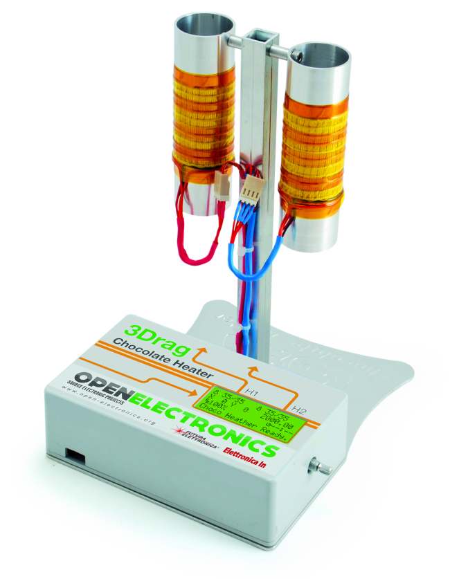
Today we present the heater capable of keeping two syringes loaded with chocolate always ready for using with the 3Drag.
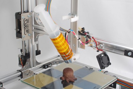
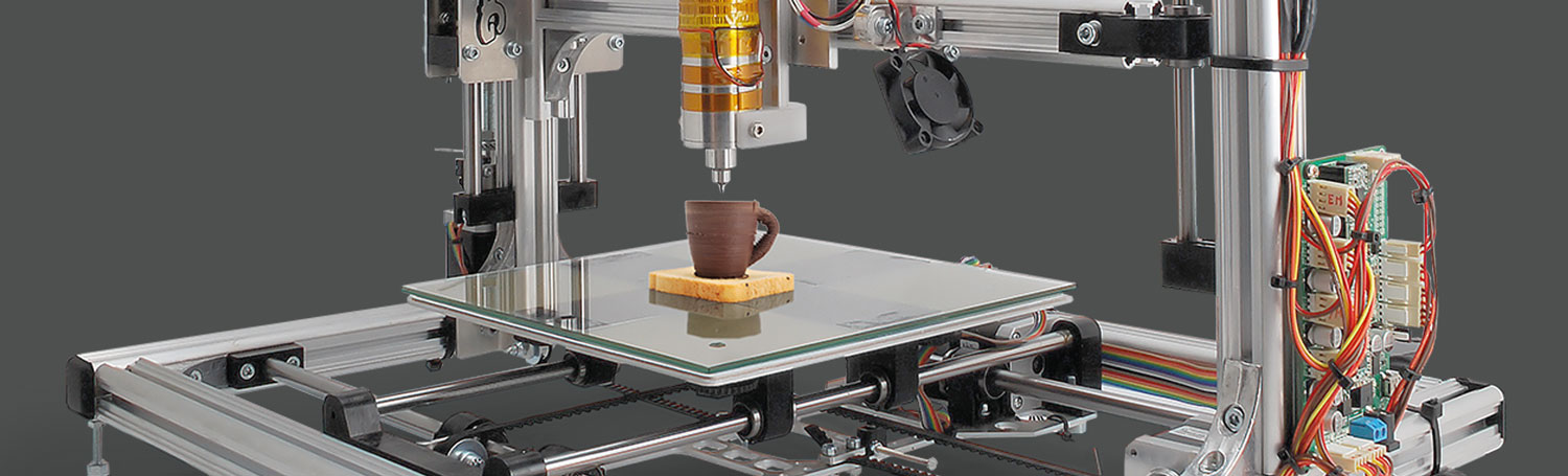
A couple of months ago we tried to surprise you by showing another astonishing transformations of our printer 3Drag: the ability to print objects and decorations with chocolate. Well, if you decided to buy the modification kit or a new 3Drag already equipped with the print head for chocolate, it means that somehow we succeeded. If today you are printing, for pleasure or business, with chocolate (milk, dark or white) you may find interesting in this accessory: this is the heater for the syringes, which allows you to keep the chocolate warm and fused in order to have refills ready to use: when you need to print many objects, you can not lose time waiting for the syringe printer to warm chocolate.
This heater is composed of a pedestal that supports two heating jackets sized to accommodate the syringe of the chocolate, identical to those mounted on the print head for chocolate.
The two syringes are mounted on the sides of a bracket and placed (without needle) upside down for two reasons: the first is that otherwise, as the chocolate melts and heats up, it would seep;
the second is that by introducing chocolate flakes or pieces to be melted, empty spaces remain inside the syringe and once the chocolate is melt they are forming air bubbles.
In this case, if the syringe is upside down, the air is pushed upward by the pressure of the weight of the chocolate and exits, as happens in the vent of the radiators, while if it is left head up, the bubbles create problems because when the syringe is loaded into the printer mechanism and the pressure of the piston moves down the chocolate mass, the air exits together with the chocolate causing the uneven deposition on the printing plate.
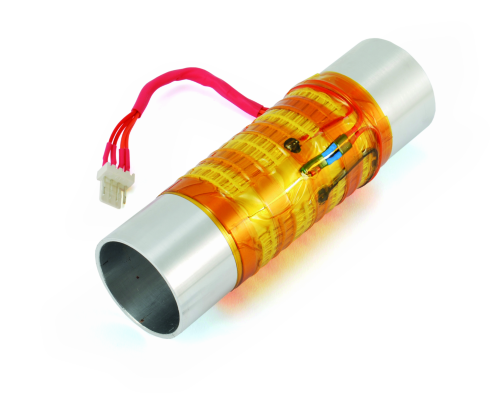
The system that we use consists in heating the body of the syringe by means of an electrical heater resistance wound on a cylinder that houses the syringe itself. The entire body of the syringe is introduced in an aluminum cylinder whose dual purpose is to support the syringe and transmit the heat produced by the heater.
Since aluminum is a good heat conductor, if it is true that transmits very well the heat to the outer side of the syringe, it is equally true that its outer surface tends to disperse and then to cool; for this reason we decided to wrap the outside of the cylinder with a heater in Kapton film.
The syringe may then be loaded in two ways: leaching into the syringe chocolate already melted at low temperature, and then inserting it into the cylinder; inserting the syringe chocolate flakes which then merge thanks to the action of the heater, once inserted into the syringe barrel.
How the heater is made
The heating system and support of each syringe consists, as mentioned, of a cylinder supported by a horizontal bracket and covered by a flexible heater that adheres to the outer surface; the heater is of the type with electrical resistance and has two wires to connect it to power.
To it, or rather to the aluminum body,it is applied a thermistor which detects the temperature reached and communicate it to the control electronics of the system, so as to stabilize the temperature of the chocolate in such a way that it is melted but not more than 33 degrees typically constituting the threshold beyond which there is a risk the loss of quenching of the confectionery product.
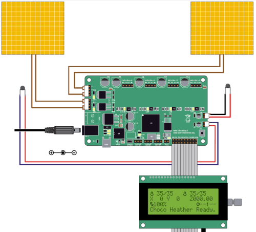
The heater control through the temperature read is operated by an electronic board which is the same one that governs the 3Drag V 1.2, but without the controller modules for stepper motors, since we don’t use them here; remember that the 3Drag controller has six outputs, four for the stepper-motor control and two single MOSFET to power the heaters in PWM (the one on extruder and the other on the heated plate).
Also it has two inputs, operated by microcontroller on-board ADC, which are used to read the two NTC thermistors, which are those in the printer to monitor the temperature of the extruder and the heated plate.
The controller board of 3Drag is therefore a more than suitable circuit to govern the syringe heater, also in consideration of the fact that it has two outputs to control resistances of heaters, both capable of delivering the ampere they need, as well as the two inputs to read the NTC in enclosures used to monitor the temperature reached on the syringe body providing feedback to the controller.
Just then realize the basic version, without mounting the stepper-motor driver modules, load in the microcontroller firmware that we have prepared on purpose, and that’s it.
Because it seemed right to manage the system in stand-alone by a person, without going through a PC, we equipped it with a control panel with a LCD display 4 lines of 20 characters and a rotary encoder with center button on knob.
The panel is the same that equips the 3Drag in the version “stand alone printer”.
The controller board
The circuit is based on a microcontroller ATmega2560 and is designed to host four driver modules for stepper motors, which we don’t use; of the three MOSFET outputs, use HEATER 1 and 2, while we ignore the third, dedicated on the 3Drag to the fan control at low voltage; the scheme is completed by a converter USB / serial interface to connect the ATmega to the computer and to a power supply stage, which completes the set.
The controller board has been presented in this post.
The control panel
The panel is connected to the expansion connector of the printer controller and it has a rotary encoder headed by a knob and a button used to reset, as well as an LCD display by 4 rows and 20 columns, and also has an adapter for SD -Card.
The display has been described (although with another form) in this post.
Assembling
To assemble the heater, we need to make or procure the electronic boards, then put together the mechanical part equipped with electric heaters.
Remember that in the controller board, drivers are not to be included.
The syringe heater must be connected to, regardless of polarity, HEATER1 contacts, while the corresponding NTC connects to THERM1; those for the other syringe must be connected in the same manner to HEATER2 and its NTC goes on THERM2.
This done, fed the control board with a power supply with plug suitable for the mounted (PL1): OK a power supply for laptops, which provides 15 volts DC and a current of the order of 4 amps.
Connect the adapter to the computer using a USB cable A / B and start the Arduino IDE to load the firmware.
When printer is off, you have to connect the cable on both sides so that there is a correspondence between the pins. Basically follow the marked wire on one side of the flat cable and make sure that if this is the side of MISO and 5V, it is on the same side too of the control panel of standalone printer.
The heater is composed by the support, by two bodies that support and heat the syringes, each formed by a cylindrical aluminum body with outer diameter of 35 mm and inner of 31.6 mm, suitably drilled on which it is wound a heating cartridge type “flat” with a supply voltage of 5 V
To assemble, take the port-syringe aluminum cylinder and applied to its external surface, the NTC thermistor, and then fix it with Kapton tape, and then wrap the cylinder also with the heating cartridge type “flat” fixing it with the usual tape Kapton.
Then fix the two complete cylinders to its support by two screws and M4.
After wiring is completed, the control panel is placed in a plastic case that must be drilled accordingly in order to host the display; on side we must make a hole to host the rotary encoder pin.
The firmware
One of the reasons why the 3Drag adopts a Marlin firmware is the innovative approach that the author has shown; for example, Marlin’s already includes modules dedicated to both the driving of the LCD and the management of the SD memory card, so in our case we have what we need. We kept the Marlin firmware also because it is an excellent base and incorporates USB management, compatibility with Repetier-Host and the PID for temperature management. It also allows you to use various types of thermistor, integrating their respective parameters to be reckoned into the equation of Steinhart Hart.
In the controller board a firmware is loaded which basically is the Marlin for 3Drag V 1.2 with the control panel designed for the stand-alone printing. It is a light version of that firmware, because we have removed the management of stepper motor; we have anyway preserved the interface routines to the control panel and those for the management of the two outputs for the heaters and of inputs connected to the thermistors used for the feedback necessary to control the temperature.
We will spend a few words to explain what has been changed in Marlin firmware: to work with the chocolate you need to keep the heater at temperatures much lower than those required for plastics.
In fact we must remember that Marlin was born to control FDM 3D printers, handling the fusion of the plastic filament and including a whole series of protections like one that prevents extrusion of the material below 170 ° C. Having to melt the chocolate at a temperature of about 33 ° C, the instruction:
#define EXTRUDE_MINTEMP 170
becomes:
#define EXTRUDE_MINTEMP 10
This change moves the protection threshold of from 170 ° C to 10 ° C and allows to fuse chocolate at 33 ° C.
Another necessary firmware change concerns the steps / mm for motor driving the extruder, imposed by different mechanics conformation of the latter. The instruction to modify is:
#define DEFAULT_AXIS_STEPS_PER_UNIT {64.25,64.25,2560,600}
in order to permit fluid extrusion of the chocolate.
The last parameter (600) indicates the rotation speed of the engine; to obtain adequate extrusion it must be reduced by 10 times, therefore the correct instruction will become:
#define DEFAULT_AXIS_STEPS_PER_UNIT {64.25,64.25,2560,60}
Another change concerns the PID for the temperature control: To prevent it from jittering excessively, we modify the parameter P, which is the statement:
#define DEFAULT_Kp 22.2
Modified in:
#define DEFAULT_Kp 32.2.
This value was calculated empirically and has given satisfactory results in our printouts.
To manage the 3Drag from the panel, we must load the correct firmware update, which is more voluminous than default firmware; no problem, however, because the 3Drag controller mounts a microcontroller with 256 kB Flash ROM, bigger than what you need. The firmware update is carried out through the Arduino IDE.

[…] http://www.open-electronics.org/syringe-heater-for-3drag-chocolate-printer/ […]
Hey there! Awesome little invention. Would you like to sell one? If so, please respond to me at briannapstevens@yahoo.com. Thank you very much! Cheers,
Brianna
I’m sorry, this is only a project, we are selling only the extruder https://store.open-electronics.org/index.php?_route_=3DCHOCO