
How to create the G-code files from any gerber file (using PCBMill software) necessary to create a PCB with 3Drag, by milling.
To create a PCB with 3Drag, by milling, you need the G-Code files for the tracks patterning and for the holes pertaining to the printed circuit board itself. In this section we describe how to obtain these G-Code files, starting with a gerber file created by using any design software for PCBs: for the conversion we use the free software PCBMill (supplied by CNCdrive company).
This software is very simple and intuitive and allows to obtain G-Code format files that can be imported without any problem in Repetier Host . The creation of the printed circuit provides the use of a chisel to make the incision of the tracks and of a drill bit with the suitable diameter for drilling. Both are to be mounted in the electric mandrel.
– The first procedure is to download the software PCBMill (PCB milling software tool) from the downloads of CNCdrive under the section “Software tools ( freeware) ” (http://cncdrive.com/downloads.html) .
– Unzip the file and install the software by double clicking on the file “Setup” ( follow the directions on-screen)
– After the installation, launch PCBMill clicking on its icon.
PCBMill settings
First of all you need to make the program settings in order to get the correct G-Code file .
Click PCBMill -> Settings (this will open the following window) :
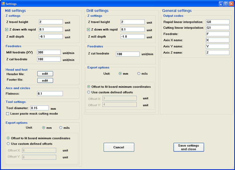
The Settings menu is divided into three parts.
The first part ” Mill settings” allows you to set some of the parameters required for the creation of the G-Code related to the incision of the tracks, such as feedrates, mill depth, etc. We recommend to keep the parameters we show (visible in the picture above). The only thing that you have to set is the tool diameter that depends on the mill (chisel) that will be used (in our case 0.15mm) .
The second part “Drill settings”, concerns the settings for CS drilling.
The third part is related to the generation of the G-Code (leave the default parameters).
Creating the G-Code files
Before using PCBMill , it is necessary to have available the gerber file related to the PCB that you want realize by milling .
Note: The Gerber file must be related to the “mirrored” printed circuit board in the same way that the “copper side” ( usually defined as Bottom Copper) remains face-up, necessary condition for a correct milling.
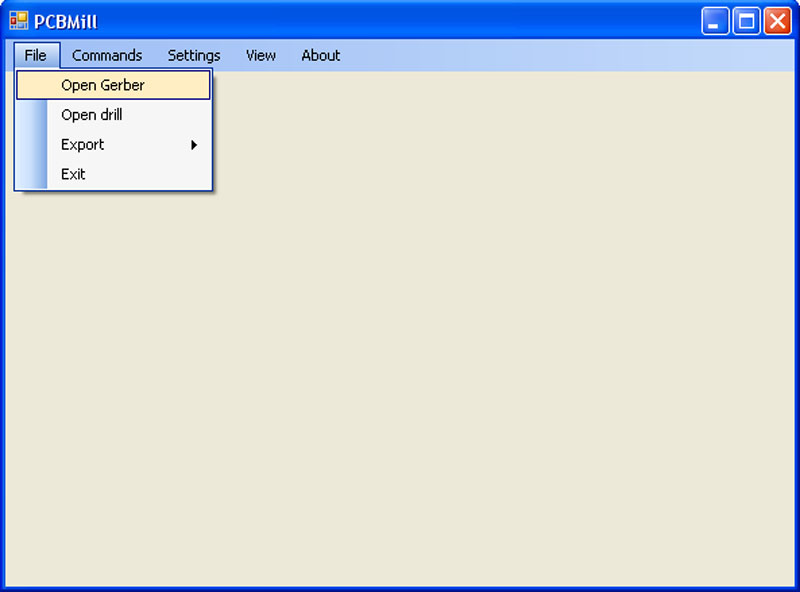
From the File menu, select Open gerber and open the files relating to the tracks (e.g. Bottom Copper.gbr ) .
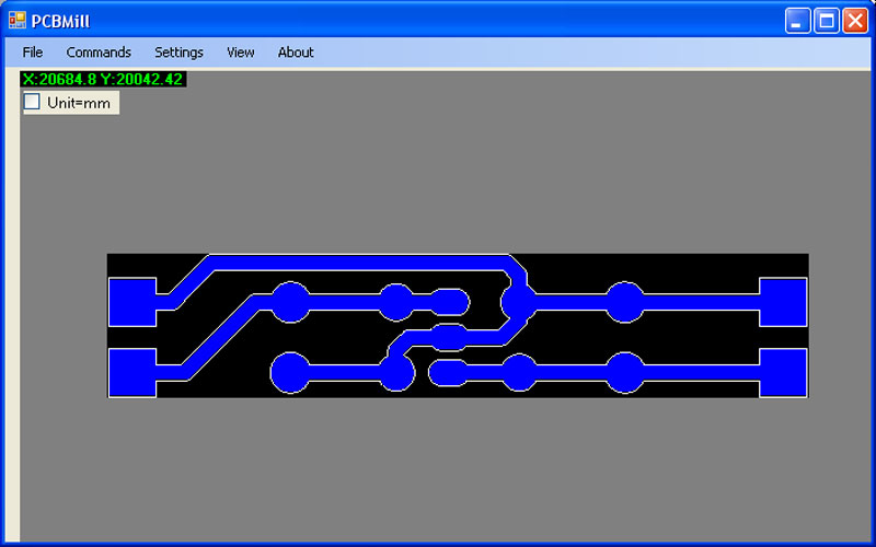
The software automatically creates the G-Code relating to the tracks patterning.
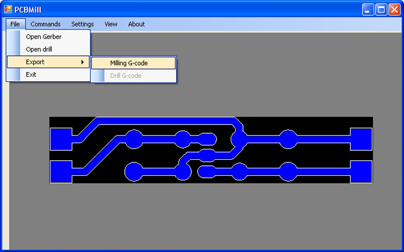
The code can be viewed by selecting the item Export -> Milling G -code:
Settings Repetier-Host and import/ G-Code modifications
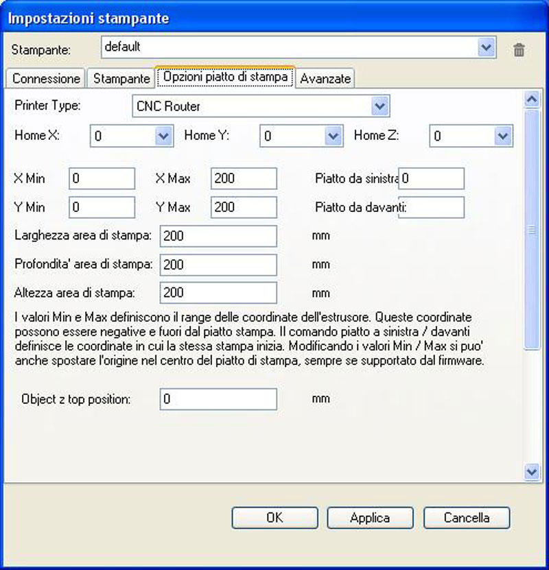
Open Repetier-Host, select “CNC Router ” (from ” Printer Settings ” in the upper right, indicated by the red arrow ):
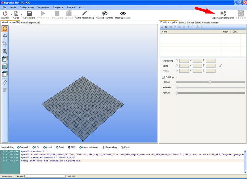
and set the parameters as follows:
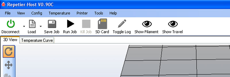
To correctly display both the incision and the tool track select “Show Filament” and “Travel Show ” .
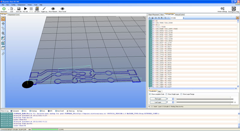
Import in the G -Code Editor of Repetier-Host (with a simple copy and paste) the G-Code on the milling of the tracks , previously generated with PCBMill , seen in the following image:
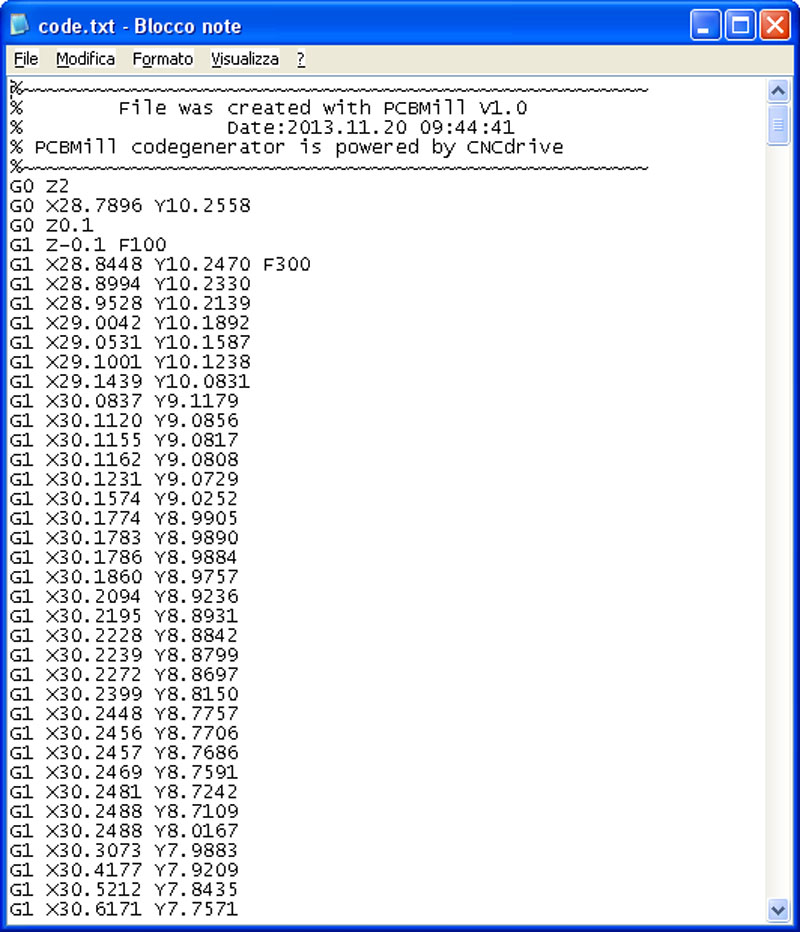
The only thing to take care of is to remove the first 5 lines of G-Code , those that begin with %
% ~ ~ ~ ~ ~ ~ ~ ~ ~ ~ ~ ~ ~ ~ ~ ~ ~ ~ ~ ~ ~ ~ ~ ~ ~ ~ ~ ~ ~ ~ ~ ~ ~ ~ ~ ~ ~ ~ ~ ~ ~ ~ ~ ~ ~ ~ ~ ~ ~ ~ ~ ~
% File was created with V1.0 PCBMill
% Date: 19/11/2013 04:36:26
% PCBMill CodeGenerator is powered by CNCdrive
% ~ ~ ~ ~ ~ ~ ~ ~ ~ ~ ~ ~ ~ ~ ~ ~ ~ ~ ~ ~ ~ ~ ~ ~ ~ ~ ~ ~ ~ ~ ~ ~ ~ ~ ~ ~ ~ ~ ~ ~ ~ ~ ~ ~ ~ ~ ~ ~ ~ ~ ~ ~
Repetier -Host is able to understand without any problem the G-Code created by PCBMill (in which the first 5 lines have been manually deleted), but before starting the incision is good to define the starting and ending point on the G-Code to impose the start and end work position to the machine. This procedure is very simple to perform in Repetier as a Start Code is expected, that Repetier will launch before running the main G-Code (that of the board processing). An End Code is also expected that will run once the work has finished.
On the right, select the tab G-Code Editor, open the drop- down menu and select Start Code :

Enter the following control lines:
G92 X0 Y0 Z0; offset of the coordinate system ( set the starting point as home)
G01 F500 ; linear movement ( sets a movement speed of 500 mm / min)
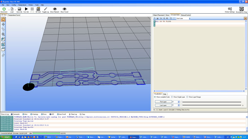
The same thing must be done for the End Code by entering the control:
G01 X0 Y0 F1200 ; linear motion (back to the point X0 Y0 with a speed of 1200 mm / min).
Preparation of CNC machine
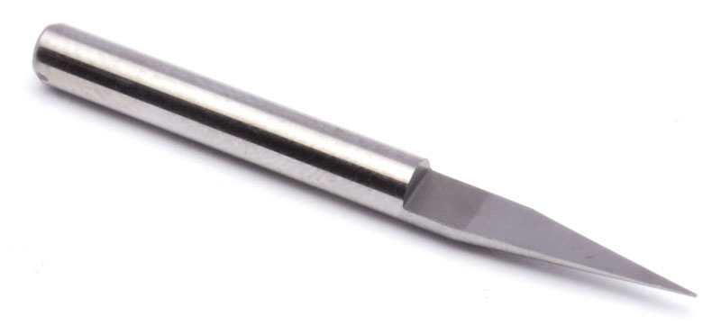
Insert and lock in the mandrel pliers the milling chisel, whose bit size must be the same of that defined in the settings of PCBMill (hard metal chisel are recommended as the fiberglass is highly abrasive!), and let it stick out as less as possible, in order to avoid vibrations and excessive run out .
Pull the tool as close as possible to the sacrificial plane so as to touch it. Move the plane in all directions to make sure that the distance from the tool is constant. Perform a pre- adjustment of the printer plate, by acting on the knobs , so that it is as much as possible coplanar with the tool.
Attach the copper strip to work on the sacrificial level, with the double-sided tape.
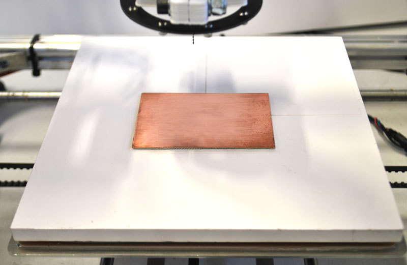
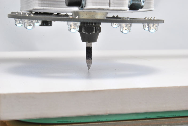
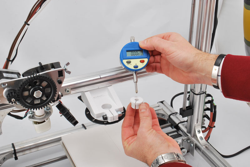
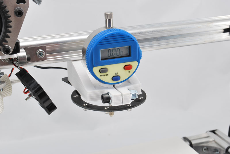
After attaching the base with double-sided adhesive is necessary to make a fine adjustment by acting on the knobs , so that the base is coplanar with the tool (to perform the procedure is possible to behave as before approaching the tool bit to the base and then slowly moving the plate in the X and Y so that the distance remains constant as possible over the entire surface of the base; or you can use an indicator with adapter – that one previously printed – inserted into the collar provided for the electric mandrel as shown in the following photos :
Start milling tracks
Lower the Z-axis (using the Repetier – Host manual control) just enough to pull the chisel close to the base (about 2-3 mm) and then adjust the X and Y axes to position the tool at the origin of the PCB that you want to mill. Now, turn on the electric mandrel, set the maximum speed then manually rotate (very slowly) the Z motor shaft to lower the machine arm until it touches the PCB with the chisel bit. The correct zero is obtained when the tool starts to “polish” the underlying copper without milling it .
Now press the ” Start Work” button of Repetier – Host and the machine will perform the patterning of the PCB as programmed. As the incision will be completed the power tool will be bring back to the starting point.
Note: It is recommended not to change this position in order to avoid a misalignment of the holes run later!
Turn off the electric mandrel.
Creating G-Code file relating to the holes
From the PCBMill File menu, select Open drill :
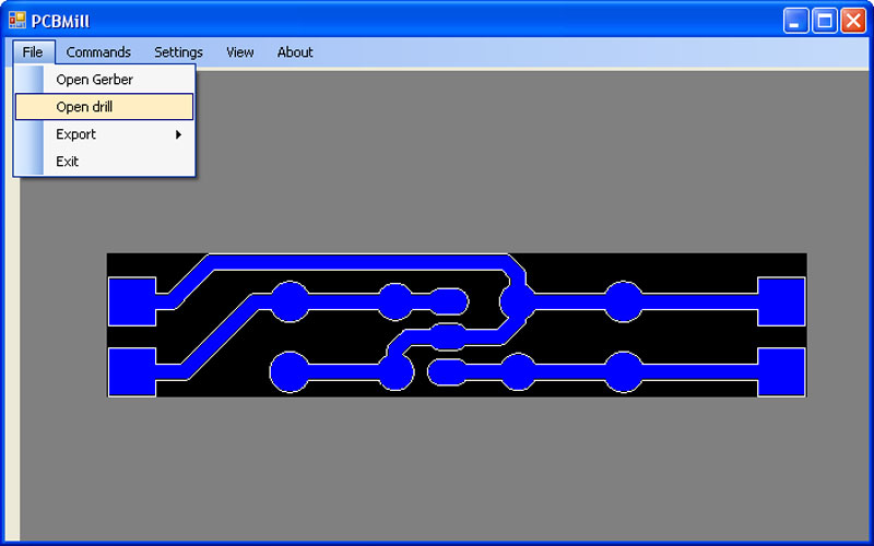
This will open a menu in which you will have to select “Read drill file”:
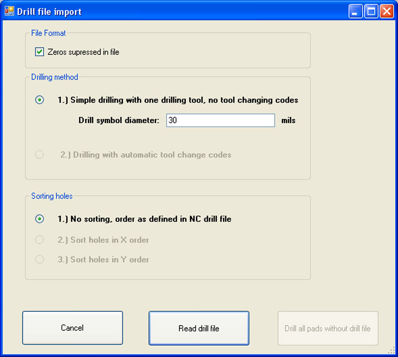
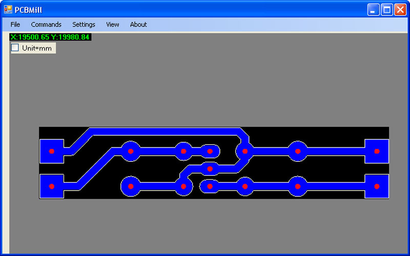
Load the file relating to holes of the PCB whose tracks patterning has been carried out by milling (e.g. Drill Data.drl).
The software will automatically create the corresponding G-Code showing the holes that will be made with red dots.
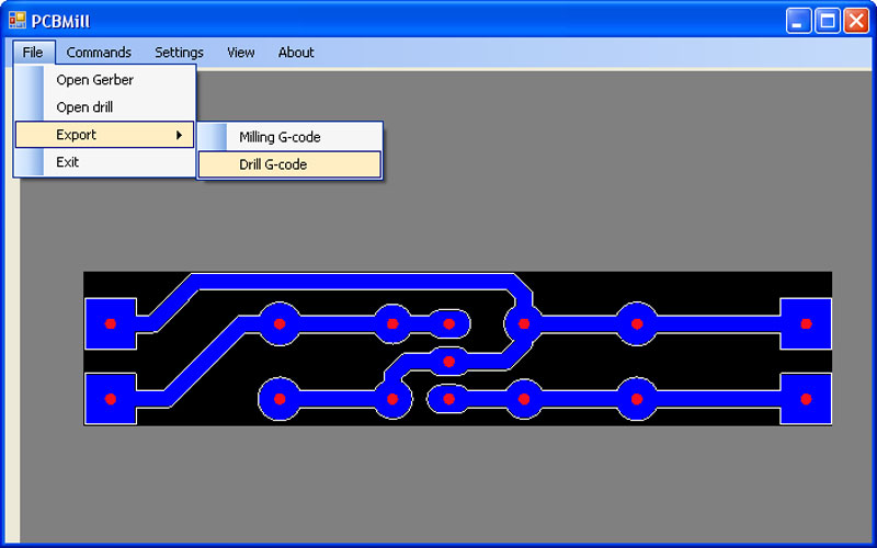
Export the file by selecting Export -> Drill G-Code .
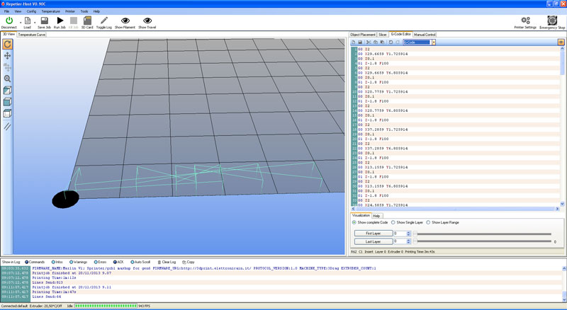
The file generated by PCBMill visible in the image below must be imported into G-Code Editor of Repetier – Host (with a simple copy and paste) .

In this case, the imported file should not be modified. In the 3D view window you will see the paths of the drilling tool (Show Filament and Show Route must be operative) .
Pick up few inches the Z-axis by acting on the manual control keys (be careful not to move X and Y!) and replace the chisel with a drilling bit of suitable diameter (e.g. 0.8 mm).
After tightening the mandrel, pull down again the Z-axis to position the bit at about 1-2 mm from the copper plate. Now, turn on the electric mandrel and rotate manually (very slowly) the Z motor shaft lowering the machine arm until it touches the PCB with the drill bit. The contact point should coincide with the contact point previously defined with the milling tool.
Note: It is recommended to do this manually so as not to break the bit due to incorrect advance selection the manual control of Repetier -Host.
Now press ” Start Work” of Repetier – Host and the machine will run the drill expected for PCB after which will reposition itself in the coordinates X0 Y0 .
Turn off the electric mandrel.
The PCB has been realized by the machine exactly as designed!

[…] How to create the G-code files from any gerber file (using PCBMill software) necessary to create a PCB with 3Drag, by milling. […]
Thanks for sharing your research.
But I have a problem to import gerber file from eagle 6.5 in PCBMil software, I have an exception error message. Do you know how to solve the problem ?
Thanks in advance
Uhmm
I’m sorry, we hadn’t this problem.
Try to ask in Eagle forum
it takes only RS242X with 2,4 2,3 res… gerber files. please do check your gerberoutput format
[…] 3Drag as a CNC milling machine: Creating G-Code from gerber filesPosted 2 weeks ago […]