Let’s Melt Metals Using the ZVS (Zero Voltage Switching) Technique Applied to a 1,000W RLC Resonant Circuit Have you ever wondered how intense the electromagnetic fields surrounding us can be?
This is a relevant question, considering we are surrounded by countless electromagnetic waves, caused by power distribution cables, radio and TV transmitters, mobile phone networks, and remote controls. Try placing a mobile phone near a landline handset or a speaker, and you’ll hear crackling.
Or walk under a high-voltage power line in the dark with a fluorescent tube and notice it lights up. These waves, invisible to the human eye, are very much present in our daily lives.
Although their effects become significant only in certain cases and depending on the irradiated power and our proximity to the source. But how powerful can an electromagnetic field be? The microwave oven in our kitchens proves that it can heat food and even produce electric arcs between the ends of aluminum foil or metallic objects.
Could such a field be strong enough to bring a metallic conductor to incandescence in a few seconds? The answer is yes, and today’s project clearly demonstrates this. It is a system that operates using three physical principles that electronics enthusiasts will know from school: magnetic induction, eddy currents, and the Joule effect.
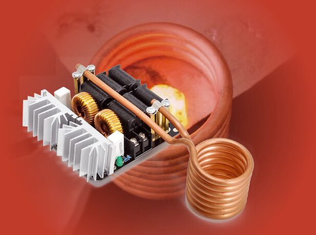
Our project demonstrates how to heat and even melt electrically conductive and especially ferromagnetic materials using a ZVS-type circuit with a nominal power of 1,000W, which can rise to 1,500W under certain conditions. ZVS stands for Zero Voltage Switching, a technique used in power electronics converters to improve efficiency.
It allows semiconductor switches to change state with near-zero voltage across their terminals, minimizing the power loss (V x I), as we’ll explain in the operating principles section. This concept is the basis for induction cooktops, widely used abroad in countries with low-cost electricity.
An induction cooktop consists of a coil through which a high alternating current flows, generating a magnetic field proportional to the current.
According to Faraday’s law, a time-varying magnetic flux induces an electromotive force in any electrically conductive body intersected by the resulting field lines.
This EMF generates eddy currents within the material of the pots or containers placed on the cooktop. These currents are also called “Eddy currents” (eddy meaning “vortex” in English), due to the swirling pattern inside the conductor.
These parasitic currents cause the Joule effect—heat generated due to energy loss. In induction cooktops, the heat warms the pot, similar to how friction dissipates kinetic energy as heat in mechanical systems. Induction cooking is a particular case: the effect of electromagnetic fields differs based on magnetic permeability, reluctance, and conductivity of the materials involved.
That explains why a metal pot (especially steel) can’t be used in a microwave oven, but meat can be cooked. Conversely, on an induction cooktop, meat won’t heat unless it’s inside a steel-based pot. In the microwave, heat is generated inside the food, while in induction cooktops, it occurs in the pot’s base. Some materials heat effectively at low frequencies; others require microwave frequencies.
Normally, eddy currents are undesirable (as in transformer core losses), but in our case, we enhance them to generate heat in the material affected by the magnetic field. In particular, ferromagnetic materials heat significantly even at the operating frequency of the circuit.
Besides heating and melting metals, the circuit has other interesting applications, such as wireless power transfer using coupled coils tuned to the resonance frequency and Tesla coil ignition circuits.
Induction Heater Circuit Diagram
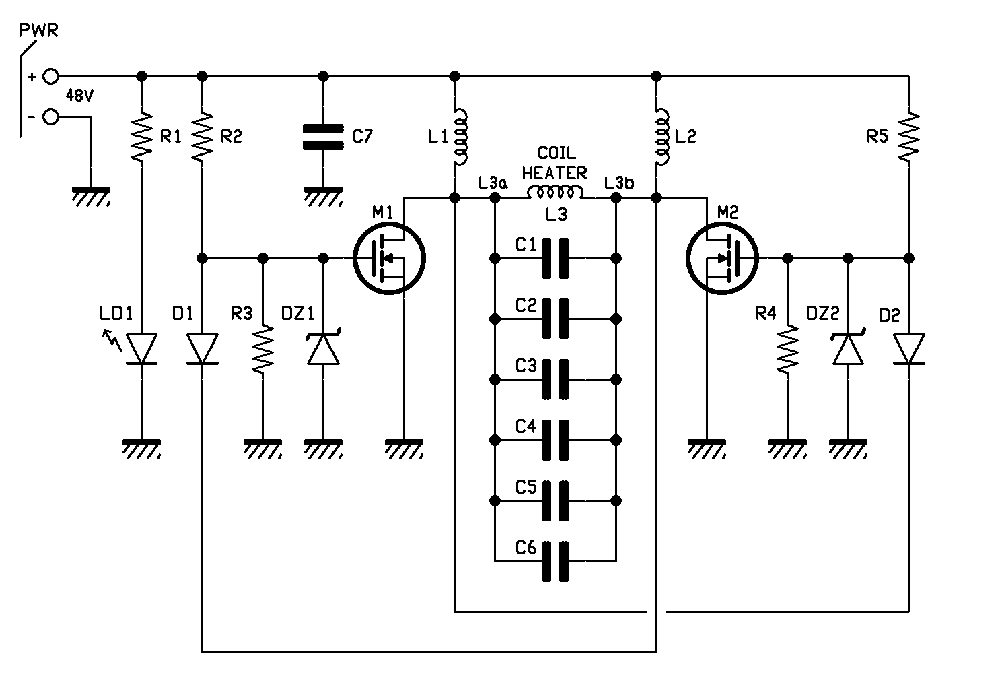
By observing the circuit diagram, we can see a symmetrical two-branch structure in the control circuit, known as a Royer oscillator, which enables self-oscillation of an RLC block at its natural resonance frequency.
The RLC block consists of an inductor (commonly called the “work coil”), a capacitor bank (called the “tank capacitor”), and the series resistance introduced by the components and wiring.
Once powered, the oscillator enters resonance. The high resonance current flowing in the work coil generates a strong magnetic field.
When the Royer oscillator is powered, even if symmetric, one of the two MOSFETs (M1 or M2) will start conducting first due to manufacturing differences. Assume M1 starts first—its drain is pulled to ground potential, forcing M2 off via the feedback diode D1, which quickly discharges the gate of M2.
The resonant circuit composed of inductor L3 and capacitors C1 through C6 presents a sinusoidal half-wave at M2’s drain, going from zero to peak and back to zero. As it returns to zero, D2 conducts, turning M1 off and switching M2 on, generating the opposite sinusoidal half-wave.
This cycle repeats at the natural resonance frequency of the RLC block. The L3 work coil carries a high sinusoidal current around 100 kHz. While this frequency produces mild heating in food, it already generates significant heating in a steel bolt, increasing with available power and induced electromagnetic field.
The MOSFETs operate in push-pull: when M1 is on, M2 is off and vice versa. This is ensured by the resonant circuit and feedback diodes D1 and D2. Simultaneous conduction would short-circuit the supply, destroying the MOSFETs.
MOSFET switching occurs with nearly zero Vds (drain-source voltage), i.e., Zero Voltage Switching (ZVS), minimizing switching losses:
Pd = Vds x Id
where Id is the drain current.
ZVS also significantly reduces the high-frequency noise naturally emitted by switching circuits.
MOSFETs M1 and M2 are Infineon IRFP260N, featuring a very low Rdson (only 40 mΩ) and high drain current (ID = 50A). They are Fast Switching types, switching quickly from full conduction (on) to cutoff, including their antiparallel protection diodes with a TRR (Reverse Recovery Time) around 400 ns.
The peak voltage in a ZVS switching circuit is calculated as:
VPEAK = SUPPLY VOLTAGE x π
Since the supply voltage is limited to 48 VDC, the maximum drain-source voltage (Vdss) is selected as 200V.
The feedback diodes D1 and D2 are MUR420, also Fast Switching, capable of carrying at least 4A and quickly turning off the associated MOSFET by discharging the gate.
The GATEs of the two MOSFETs are driven by power resistors R2 and R5, each valued at 470 ohms.
To protect the MOSFETs from overvoltage and overcurrent, two Zener-resistor pairs are used: R3/DZ1 and R4/DZ2. R3 and R4 are 10 kohms; DZ1 and DZ2 are 12V – 1W.
LED LD1 indicates the presence of power and is powered through the series resistor R1, 4.7 kohms, to limit current.
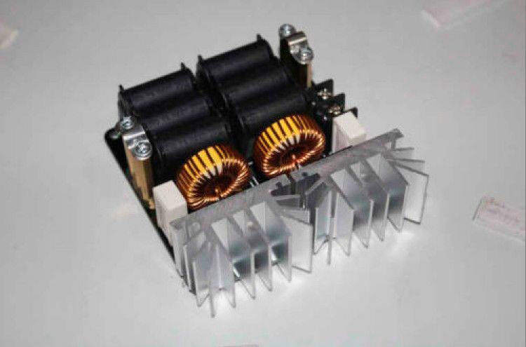
Inductors L1 and L2 are 100 µH and serve to suppress switching voltage spikes (“spikes”) that could destroy the MOSFETs. They are wound on toroidal cores with a maximum current rating of 13A.
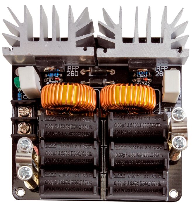
Capacitors C1, C2, C3, C4, C5, C6 are MKP polypropylene capacitors, chosen for their ability to withstand high currents and voltages during resonance while minimizing losses.
In this design, the resonance capacitance is approximately 2 µF, achieved by paralleling six 0.33 µF capacitors rated at 630V.
The work coil (Fig. 1), into which the object to be heated/melted is placed, is made of 6 turns of 6 mm diameter hollow copper tube with 0.8 mm wall thickness. It is air-wound to handle high currents, dissipate generated heat effectively, and reduce skin effect losses at 100 kHz.
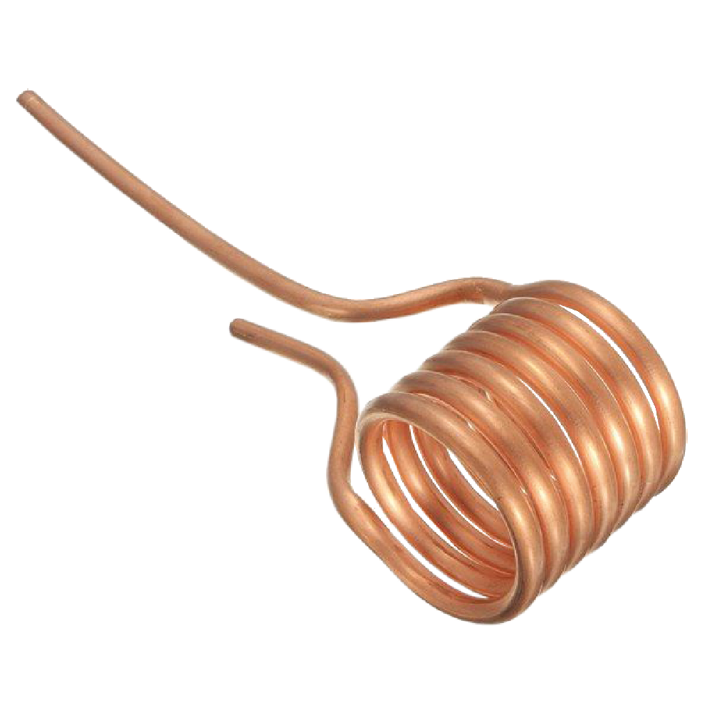
The turns must not touch each other (since the copper is bare), otherwise short circuits will form, reducing the number of effective turns and altering inductance.
The theoretical inductance of the work coil is about 1.26 µH, though this may vary depending on the length of the horizontal leads connected to the capacitors.
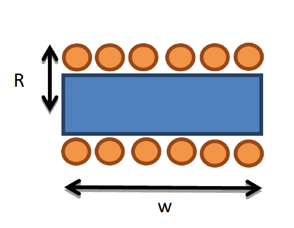
To calculate the theoretical self-inductance, you can use the formula (refer to Fig. 2):
L = µ₀ * N² * π * R² / w
Where µ₀ is the permeability of free space (µ₀ = 4π * 10⁻⁷ H/m),
N is the number of turns (in our case, 6),
R = 2.5 x 10⁻² m and w = 7 x 10⁻² m, hence L ≈ 1.26 µH.
To calculate the theoretical resonance frequency, use the formula:
fR = 1 / (2π * √(L * C)) = 100.3 kHz
Where L = 1.26 µH, C = 2 µF.
Assembly Layout
Component List
C1: 0.33 µF 630 V~ pitch 30mm
C2: 0.33 µF 630 V~ pitch 30mm
C3: 0.33 µF 630 V~ pitch 30mm
C4: 0.33 µF 630 V~ pitch 30mm
C5: 0.33 µF 630 V~ pitch 30mm
C6: 0.33 µF 630 V~ pitch 30mm
C7: -
R1: 4.7 kohm
R2: 470 ohm 5W
R3: 10 kohm 1%
R4: 10 kohm 1%
R5: 470 ohm 5W
L1: 100 µH inductor
L2: 100 µH inductor
L3: 1.26 µH coil
M1, M2: IRFP260N
D1: MUR420
D2: MUR420
DZ1, DZ2: 1N4742
DL1: 5 mm green LED
Practical Assembly
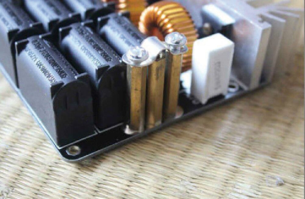
To mount the coil, three 6 mm golden hexagonal standoffs, each 40 mm long, are used. The two lateral ones are fastened (using 4MA screws) with an iron clamp that secures the ends of the work coil. Loosen the screws holding the two standoffs (Fig. 4), insert the ends of the work coil into the metal support so that the coil is oriented toward the power supply terminal block marked + / -.
Position the work coil so that less than 1 cm of tubing extends from the standoff support, and tighten the screws (Fig. 5).
Measurements
The current circulating through the work coil has an RMS value of approximately 100 A.
With such a high current, the magnetic field is significant, and all nearby objects are exposed to its field lines—hence, sensitive electronic devices might experience interference.
The magnetic flux density B can be calculated with the formula:
B = µ₀ * N * I / L = 10.7 mT = 107 gauss
Where N = 6, I = 100 A, and L = 1.26 µH.
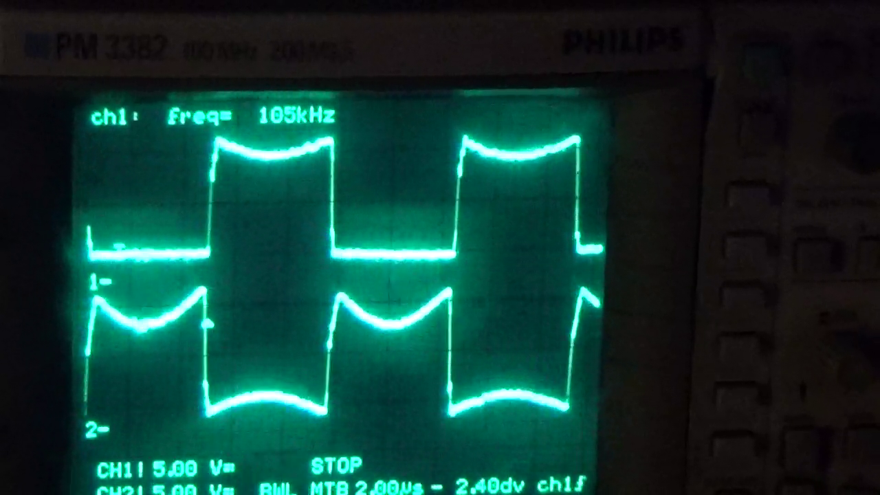
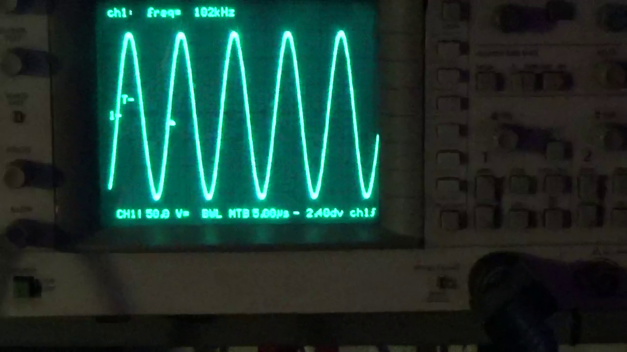
Fig. 7 shows the oscilloscope waveforms of the GATE-SOURCE voltages of M1 and M2. As can be seen, they are perfectly in antiphase:
Before the GATE voltage of M2 reaches the high level and M2 turns fully on, M1’s GATE voltage is already low, ensuring M1 is off and preventing simultaneous conduction, which would destroy the MOSFETs.
Fig. 8 shows the voltage applied to the work coil, reaching around 150V peak and maintaining a perfectly sinusoidal waveform, thanks to the parallel RLC resonant circuit.
Finally, Fig. 9 shows the current drawn by the circuit at an input voltage of 48 VDC, which is approximately 17 A.
The measurement was made by detecting the voltage drop across a 0.06 ohm shunt resistor (obtained by paralleling three 0.18 ohm resistors) using a digital multimeter, with a metal object inserted in the work coil.
We wish you good luck and remind you once again: with proper care and attention, this circuit can provide you with impressive and rewarding experiences.
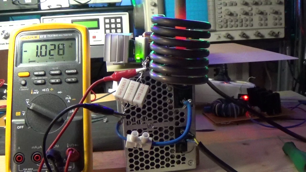
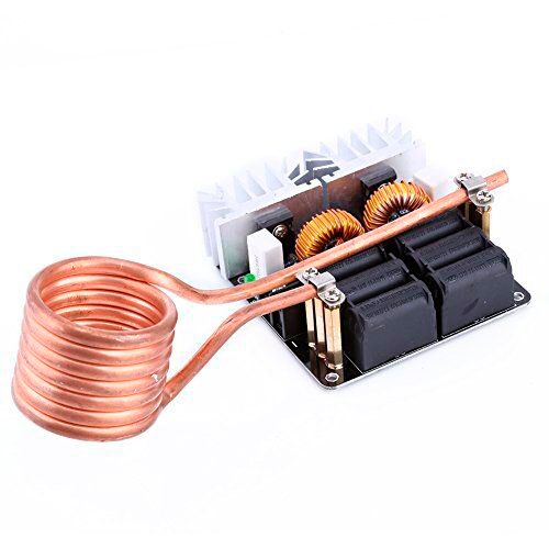
Fig. 5 Work coil mounted on the circuit.
Usage
The circuit must be powered with a DC voltage between 10 and 48 V and with sufficient power. If using the maximum voltage of 48 VDC, we recommend a power supply rated at least 1,500 W.
Insert the positive and negative wires of the power supply into the terminal block, checking the polarity, and tighten the screws.
Power the circuit via terminals + and – and check that the green LED LD1 lights up, indicating input voltage presence.
At this point, the resonance current starts flowing through the work coil at approximately 100 kHz.
If powered at the full 48 VDC without any metal object inside the work coil, power consumption remains under 500 W;
however, when a conductor is inserted, depending on its material, size, shape, and position, power consumption can vary greatly up to 1,500 W.
Choose the conductor to be inserted—like a metal screw—hold it with pliers (do not get too close to the coil) to avoid burns.
Insert the conductor slowly into the work coil, ensuring it doesn’t touch the inner coil walls.
Keep the conductor vertical inside the work coil.
The inserted conductor acts as the transformer’s secondary, with the work coil being the primary winding. Being inside a solenoid, the conductor is exposed to a strong magnetic field.
Within seconds, due to the Joule effect, the conductor heats up and glows with typical incandescent orange-yellow tones (Fig. 6).
This condition can be maintained for tens of seconds. However, be extremely careful as temperatures rise rapidly—do not touch the conductor, coil, or heatsinks directly to avoid burns.
After several minutes of use, the work coil will begin to darken, eventually turning nearly black from the heat generated. This will not affect its performance.
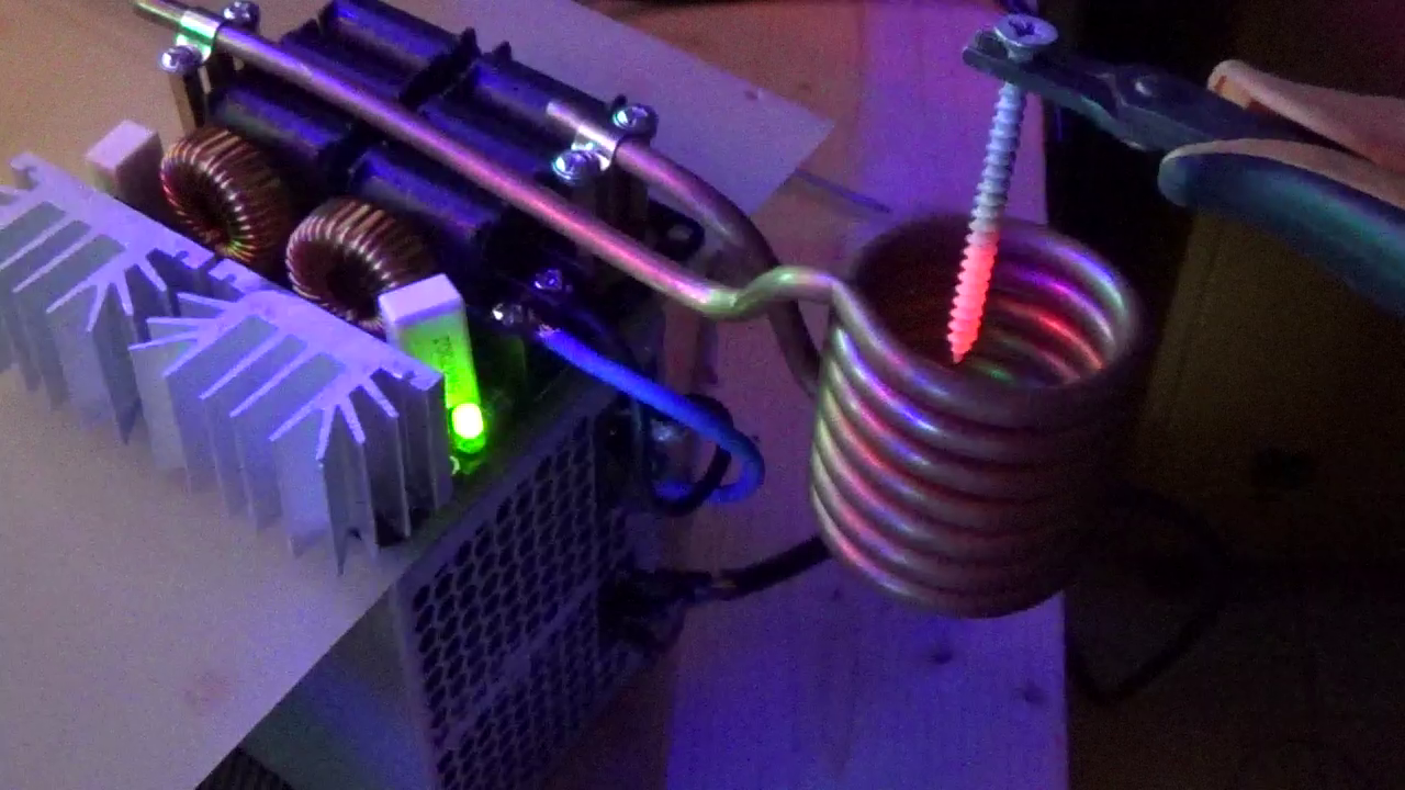
Fig. 6 Position the object inside the coil.

Wow, this melts nails and steel in seconds!! xD
Solid DIY project with great schematics, Boris! Perfect for anyone into high-power electromagnetics.