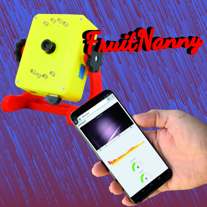
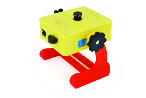
The electronic guardian who watches over our baby’s rest periods and environmental conditions of their room.
Sometimes, when “browsing” the web in search of solutions to common problems, we happen to run into projects which are decidedly significant from the point of view of the use of resources, aimed at solving a problem that has arisen. In our case, it is about ensuring that our baby, during rest periods, enjoys a peaceful sleep and in the best possible environmental conditions.
The project that intrigued us was developed by Dmitry Ivanov, an engineer in the construction industry, who specialized in the area of building automation. In his free time, among other things, he delights in developing computer applications, such as the one named FruitNanny, which we came across by visiting his site and which we present in this article. We are very intrigued by its creation as it is aimed at solving a very common problem, which as supervising the rest of a child, devising a solution that exceeds the limits of similar even commercial solutions and, moreover, offers excellent opportunities from an educational point of view. The replication of a project like this allows us to understand, for example, the difference of the application fields covered by a microcomputer with an operating system (for example Raspberry Pi, with Raspbian operating system), compared to a form based on a monoprogram microcontroller like those belonging to the widespread Arduino family. In this second case, the application consists of a single program, which must express all the functions necessary for the management of our application. In the event that it is necessary to manage functions based on events or precise timings, we will have to take responsibility for all the conditions of competition and conflict that may appear. Moreover, in general, the microcontrollers are equipped with a single-processor CPU. This obliges us to evaluate and take into account the processing times of the individual functions, so as not to overlap with events, external interruptions and internal timings. On the other hand, guarantees are offered in the case of greater jobs, voltage drops and shutdowns… awkward. Excellent for use in automotive, industrial automation and anti-theft devices. Microcomputers equipped with an operating system, on the other hand, are particularly suitable for managing situations where different heterogeneous applications are called to work collaboratively to provide an integrated and homogeneous solution. This is the case for a system for collecting data from various sensors that are acquired and processed by individual specialized applications, and then stored in a single storage system and/displayed in a distributed way, by means of web applications. An architecture of this type consists of many modules, each capable of both functioning individually and collaborating with other exchanging data and messages. Since there are many modules that need to work almost simultaneously, these architectures take advantage of microcomputers equipped with multiprocessor CPUs and high-level software systems able to manage the available resources, assigning them to different applications as needed. In particular, this task is performed by operating systems such as GNU / Linux in the Raspbian distribution for Raspberry Pi. If well designed, these architectures, in the case of bottlenecks on dedicated resources, or the need to expand loads and functionality, can be scaled by installing the different modules on separate computers, with powers and resources appropriate to a load of each module.
Project description
Returning to our project, this is an architecture that has the purpose of supervising a child during rest. The reference environment is a dark room, or at least in dim light. The aim of the project is to monitor the child with a camera that captures any “abnormal” movements, for example, an early awakening. If by chance the baby starts crying, you also want to acquire this condition by means of a microphone. Finally, you want to monitor the room’s environmental parameters such as temperature and humidity. All this becomes useful when this information is made available on the network through a web server.
In particular, regarding the acquisition of video images, being a room in dim light, we must necessarily orient ourselves towards an infrared camera. For greater visibility, it is also advisable to equip our system with LED lighting that emits in the infrared field, in order to “illuminate” the room without “waking up” the child with visible light. Since we will not always be glued to the image of the room, we want to be able to turn on and off the lighting at will.
Finally, to simplify the “user” interface, we want to group all the information, images, sounds and measured quantities into a single web page that can be used by any device with a browser such as a PC, tablet or smartphone. As you can guess, what we present is a typical project of “integration” of devices and technologies. The skills required to complete these projects are not focused solely on the implementation of programs but on the ability to choose, install and configure different applications, so that they work together. A good knowledge of the GNU / Linux environment, and Raspbian in particular, is certainly a help in solving any difficulties that may arise.
As for a basic introduction to Raspberry Pi and the Raspbian environment, you can refer to the book “Enter the world of Raspberry Pi 3” and to the numerous articles already published in the magazine. Finally, a lot of help and suggestions can be found on the web.
Connections diagram

Fig. 1
In Fig. 1 you can see the outline of the solution proposed in the project, modified, compared to the original design, based on the components that we could find with greater ease. In Fig. 2 the references of the connections to the Raspberry Pi GPIO are visible. The “hardware” configuration of “FruitNanny” is quite simple. The basic element is the Raspberry Pi microcomputer, in version 3. If you already have a Raspberry Pi 2 in the “drawer” and want to allocate it to this project, that’s fine, also because we recommend that you connect Raspberry Pi to your local home network via cable Ethernet, making WiFi functionality superfluous. If for several reasons you prefer to connect Raspberry Pi via WiFi then it is preferable to use a Raspberry Pi 3 which natively has WiFi connectivity. We have grouped in this description both the list of devices used and the creation of electrical connections. The recommendation is to make sure that the Raspberry Pi is disconnected from the power supply before making the connections.

Fig. 2
As you can see in Fig. 1, the infrared microcamera is connected to the microcontroller, in our case, the model 2846-RASPBERRYCAMIR available on open electronics. Alternatively, you can use the official Pi Camera NoIR infrared camera. As for the infrared illuminators we used two FT1336K kits, connected together to form an illuminator with eight IR LEDs. Switching on and off takes place in the conducting or interdiction state, the BS170 MOSFETs present on the circuit, respectively bringing the Gate of the Mosfets to the high (3.3V) or low (GND) level. The IR illuminators must be connected in parallel as shown in Fig. 3 and connected with cables, with a female connector, to the Raspberry Pi GPIO. In particular, the positive and negative of the power supply must be connected, respectively, to the physical pins 2 (+ 5V) and 6 (GND) of the GPIO connector while the signal cable (Gate of the Mosfet BS170) to the physical pin 3 (GPIO2).

Fig. 3
The flat cable of the micro camera is inserted into the Raspberry Pi CSI (Camera Serial Interface) slot located between the HDMI connector and the audio/video output jack. To insert the connector, lift the white or black locking frame according to the models of the CSI connector by gently pulling up the side fins. Carefully insert the flat cable of the camera into the CSI connector taking care to keep the blue part facing the audio/video jack and the silver connectors towards the HDMI connector, as shown in Fig. 4. Check that the flat cable is fully inserted and aligned, then close the block frame.

Fig. 4
For the temperature sensor, we used the TEMPHUM board with the DHT11 onboard sensor that allows it to measure temperatures between 0° C and + 50° C and relative humidity from 20% to 90%. It communicates with Raspberry Pi through a single-wire serial interface, in the project corresponding to the physical pin 18 which corresponds to the BCM GPIO24 pin. Communication uses a protocol based on a series of initial handshaking pulses followed by a sequence of pulses for the transmission of the values read by the sensors, the length of which is shown to be “zero” or “one”. The positive and negative voltage is respectively drawn from the physical pins 17 (+ 3.3V) and 14 (GND).
The USB microphone, type 2846-USBMICMINI, is simply plugged into a USB connector.
Application architecture
Now that everything has been assembled and all the connections have been checked at least a couple of times, it is time to think about the software architecture.
Our goal is to remotely control, through a web browser, the data collected by the “environmental” sensors connected to Raspberry Pi. In particular, we will have to manage:
- Video streaming from the infrared camera;
- Audio streaming from the microphone;
- Numerical data coming from the reading of temperature and humidity sensors;
- Finally,[highlight color=”eg. yellow, black”]…[/highlight] we want the possibility to remotely turn on and off the infrared illuminators.
At this point, there is the main problem in the design of integration applications between the physical world (sensors and actuators) and a graphical user interface. Once a general scheme has been defined that represents the flow of information and the required functionalities, it is appropriate, both from an economic point of view and a production time, to try to cover most of the features with existing packages and available in the repositories of the operating system distribution, in our case Raspbian, or on the various websites of sensor manufacturers and/or implementers of open source and free use applications (the two conditions do not always occur jointly). Without going into too much detail, because what we are presenting is an article and not a large tome on the design of complex applications in the GNU / Linux world, we list the choices made in the project, which you can see in graphical form in Fig. 5.
- As far as the operating system is concerned, the choice could only fall on GNU / Linux and in particular on the Raspbian distribution in the Stretch version, the latest available from the Raspberry Pi Foundation;
- For the management of the web application, it is necessary to use a web server, that is an application, in permanent execution, able to acquire the requests from the pages and data browsers that connect, and to reply using pre-packaged pages or recall the applications that can produce the data if necessary; in our case the audio and video streams and the temperature and humidity values coming from the sensors. The solution adopted in this project is a mixture of the two technologies. For this function we use the “Nginx” package a very light and configurable web server that also optimally performs proxy functions, which we will use for the transmission of video and audio streams within the “container” page;
- The streaming coming from the infrared camera and the microphone are, by their nature, multimedia streaming or continuous flows of packets that must be transmitted and received in sync, so as to avoid seeing images… slowed down and streams of sound in… hiccups. For this functionality, the “GStreamer” package was used as a library specialized in the construction of “pipelines” (transport flows) for the transmission of multimedia data. In particular, the video stream is transmitted using the H264 standard without modification, while the audio stream is compressed using the “Opus” codec. Both media streams are transmitted via TCP / IP sockets (UDP packets);
- To link streaming audio and video streams to the browser on the user device, the “Janus WebRTC gateway” package is used. As the name implies, this package is a gateway that is a device passing between one application and another, in particular between media streams and the HTTP protocol. The acronym RTC stands for Real Time Communication;
- To satisfy the requests of temperature and humidity data and to perform the commands for switching the infrared illuminators on and off, it is necessary to use an application server; an application running permanently that receives the requests from the browser and performs the required readings and commands. This is the part created personally by Dmitry Ivanov as part of the FruitNanny project and available on his GitHub repository. The application is made in NodeJs, an event development environment, programmable in javascript. Also in his repository are the python scripts that physically perform the sensor readings and the bash scripts to turn the illuminators on and off. Kindly, all the configuration files of the various packages were also provided;
- To simplify the reading of temperature and humidity sensor data, using the monofilament serial interface, the “Adafruit_Python_DHT” library will be used, which provides the basic software to interface the sensors and the wrapper in order to use the library functions in the python programs.
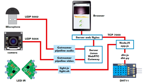
Fig. 5
Software installation
With the hardware assembled and a general outline of the architecture to be implemented, you can start to install the different components of the architecture, configuring them so they can interact with each other to achieve the goals of our project. To solve the graphics problem related to the representation of the single commands, since simply inserting them in the columned text of the article pages led to returns and very confusing blocks of commands, we preferred to provide you with lists of commands in dedicated boxes like you use for programming listings. We divided the blocks of commands by topic and entered the commands, when possible, as single commands. Only when necessary, will you find the commands in the chain, which can occupy more than one line. In the blocks, we have included all the commands necessary to install all the required packages and their dependencies, with reference to the Stretch version of the Raspbian operating system. Since Raspbian is an operating system, like all the GNU / Linux distributions in general, in continuous evolution, some packages may already be included in the default configuration. In other cases, especially in the case of the audio chain, due to subsequent updates, it may be necessary to intervene on the configuration of some elements. In these cases, the web, and experience are certainly helpful. After all, the reason why we present this project is mainly educational.
Connect Raspberry Pi to the network. Decide whether to use a terminal window from the PIXEL graphical interface, using monitor, keyboard and mouse, or by connecting via SSH remotely.
Turn on the Raspberry Pi and, from the terminal window, run the update commands to the latest release of the operating system, including the kernel. Type the commands:
sudo apt-get update
sudo apt-get dist-upgrade
sudo rpi-update
Then install the basic packages necessary for perfecting the Raspbian operating system for the purposes of our project. In practice, execute the commands listed in Box 1 in sequence. You will notice that for some packages the “apt” manager will find that they are already installed and updated. No problem, continue with the next command. As new releases of Raspbian are released, many packages are included by default. However, our list contains all the necessary ones.
Box1
sudo apt-get install git
sudo apt-get install libraspberrypi-dev
sudo apt-get install autoconf
sudo apt-get install automake
sudo apt-get install libtool
sudo apt-get install pkg-config
sudo apt-get install alsa-base
sudo apt-get install alsa-tools
sudo apt-get install alsa-utils
Now it is time to enable the camera. For this operation, we will use the features made available by the Raspbian configuration application. To execute it, type the command:
sudo raspi-config
From the menu select “Interfacing Options” and on the next page the item “P1 Camera”, as shown in Fig. 6.

Fig. 6
Select “Yes” on the configuration page and then “OK” on the confirmation request page.
The next operation that we are going to describe necessarily requires the graphical desktop, which, in turn, requires the use of a monitor, keyboard and mouse, or a remote desktop connection. The configuration serves to make the operating system recognize the USB microphone as the default sound acquisition device. From the menu, open the “Audio Device Settings” configuration feature as shown in Fig. 7.

Fig. 7
Select the USB microphone from the top of the page (Fig. 8).
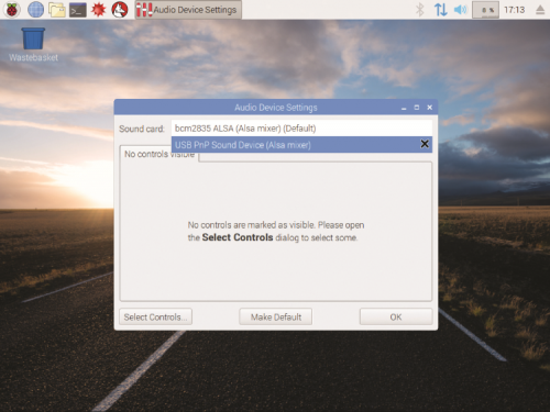
Fig. 8
In the subpage check the item “Microphone” (Fig. 9).

Fig. 9
On the new page, set the acquisition volume level for the microphone. Then click on the “Make default” button and finally confirm with “OK” (Fig. 10). This is everything for the microphone. Now you can continue with installations and configurations.
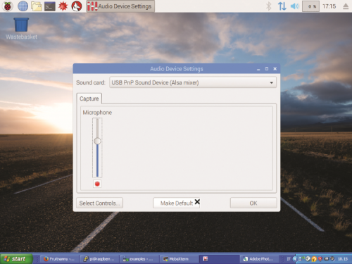
Fig. 10
Download the software created by Dmitry Ivanov from his GitHub repository. The commands are listed in Box 2. The repository contains the programs and modules needed to build the web application, some configuration files for the servers and other additional tools. We will see their use later. As you can see in Box 2, the software is initially installed in the folder /home/pi/.
Box2
cd /home/pi
sudo mkdir fruitnanny
sudo chown pi:pi fruitnanny
git clone https://github.com/ivadim/fruitnanny
chmod -R 755 /home/pi/fruitnanny
In the “/home/pi/fruitnanny/bin/folder”, the video.sh and audio.sh files contain the commands for setting the video and audio pipelines for the transmission of the respective streams. We will have to modify these files later.
To install GStreamer, the video and audio stream manager, run the commands listed in Box 3. GStreamer is a media streaming infrastructure. Applications that use this library can do (almost) anything in the multimedia environment, from real-time sound processing to video playback. Its architecture, based on plugins, allows you to add new types of data or playback capabilities simply by installing the affected plugins, in our case those for the management of video and audio.
Box3
sudo apt-get install gstreamer1.0-tools
sudo apt-get install gstreamer1.0-plugins-good
sudo apt-get install gstreamer1.0-plugins-bad
sudo apt-get install gstreamer1.0-plugins-ugly
sudo apt-get install libgstreamer1.0-dev
sudo apt-get install libgstreamer-plugins-base1.0-dev
sudo apt-get install gstreamer1.0-alsa
For a change, the official GStreamer repository does not provide the plugins needed to recognize the CSI cameras for Raspberry Pi. Fortunately, an Australian, Mr Jan Schmidt, has created and made available in his GitHub repository, the source of the “gst-rpicamsrc” package, a wrapper built “around” the “raspivid” and “raspistill” features that can transform the flows coming from Pi Camera in the format expected by GStreamer. Since the package is in source format, after downloading it, it is necessary to compile it and install it. Fortunately, a bash script provided by Jan Schmidt greatly facilitates the process. The commands can be found in Box 4.
Box4
git clone https://github.com/thaytan/gst-rpicamsrc /tmp/gst-rpicamsrc
cd /tmp/gst-rpicamsrc
./autogen.sh --prefix=/usr --libdir=/usr/lib/arm-linux-gnueabihf/
make
sudo make install
The Janus RTC Gateway must also be installed from sources. The sequence of commands is available in Box 5. Remember that the GatewayRTC is intended to convey the video and audio streams to the web server in order to be played in the browser of the connected person. The first part is aimed at installing a series of packages that are required for the compilation and execution of the Janus Gateway. The second command block allows you to download the Janus sources from the GitHub repository. Finally, the third command block allows you to compile the Janus Gateway, run the build and install the executables and compilation files in the destination folders.
Box5
1- Install prerequisite packages
sudo apt-get install libmicrohttpd-dev
sudo apt-get install libjansson-dev
sudo apt-get install libnice-dev
sudo apt-get install libssl-dev
sudo apt-get install libsrtp-dev
sudo apt-get install libsofia-sip-ua-dev
sudo apt-get install libglib2.0-dev
sudo apt-get install libopus-dev
sudo apt-get install libogg-dev
sudo apt-get install pkg-config
sudo apt-get install gengetopt
sudo apt-get install libsrtp2-dev
2- Janus source exhaust
git clone https://github.com/meetecho/janus-gateway /tmp/janus-gateway
cd /tmp/janus-gateway
git checkout v0.2.5
3 – Compilation and installation
sh autogen.sh
./configure --disable-websockets --disable-data-channels --disable-rabbitmq --disable-mqtt
make
sudo make install
The Janus configuration files suitable for our project are available in the folder:
/home/pi/fruitnanny/configuration/janus/:
- janus.cfg – General configuration file for Janus. With respect to the original configuration file, some unnecessary plugins are disabled in our project;
- janus.transport.http.cfg – Enable access to Janus by HTTP protocol;
- janus.plugin.streaming.cfg – Configure the audio and video streams to present them on TCP port 5002 for audio streaming and 5004 for video streaming respectively.
To configure the Janus RTC Gateway correctly, simply copy the configuration files listed above to the Janus configuration folder. The commands are shown in Box 6.
Box6
sudo cp /home/pi/fruitnanny/configuration/janus/janus.cfg /usr/local/etc/janus
sudo cp /home/pi/fruitnanny/configuration/janus/janus.plugin.streaming.cfg /usr/local/etc/janus
sudo cp /home/pi/fruitnanny/configuration/janus/janus.transport.http.cfg /usr/local/etc/janus
The next step consists of the installation of NodeJs and some additional packages, to allow communication between the programs that perform the sensor readings and the web server, so as to expose the graphic representation of temperature and humidity on the web page. All listed in Box 7.
Box7
cd /home/pi/fruitnanny
curl -sL https://deb.nodesource.com/setup_6.x | sudo -E bash -
sudo apt install -y nodejs
stando in /home/pi/
npm install express
npm install ejs
In these times privacy is can never be too much, especially when it comes to minors, so it is good to encrypt the communication of audio and video streaming using the HTTPS protocol. To do this it is necessary to generate an SSL certificate (Secure Socket Layer) that contains the cryptographic keys and allows to certify the communication. For this, we must use the commands indicated in Box 8. The same certificate will be used to access, from the browser, the Nginx web server using the HTTPS protocol.
Box8
cd /usr/local/share/janus/certs
sudo openssl req -x509 -sha256 -nodes -days 365 -newkey rsa:2048 \
-keyout mycert.key -out mycert.pem
During the generation of the certificate, you will be asked for some information that allows you to customize and make the certificate unique. Answer the questions as you are asked until the procedure is complete.
In order to access the GPIO for reading the sensors and for switching on and off the infrared illuminators, without having to resort to the user “root”, it is necessary to involve the user with whom we connect to Raspberry Pi (usually “pi”) to the “gpio” group. This is achieved with the command:
sudo adduser $USER gpio
We anticipated that the DHT11 temperature and humidity sensor communicates with a customized single-wire serial protocol. Adafruit has created a library that makes the serial protocol transparent and allows acquisition of sensor data directly from python programs. All that remains is to install the library, taking it from Adafruit’s GitHub repository.
The commands are in Box 9.
Box9
modifigit
clone https://github.com/adafruit/Adafruit_Python_DHT /home/pi/Adafruit_Python_DHT
cd /home/pi/Adafruit_Python_DHT
sudo apt-get install build-essential python-dev python-pip
sudo python setup.py install
One of the features needed in an “autonomous” application or, as we say “stand-alone” is that everything starts automatically when the device that hosts it is turned on. To do this there are several possibilities. The most professional is to entrust this task to the process of initializing all system processes at the end of the boot phase. The process is “systemd” a noticeable improvement, included in the latest versions of the Raspbian distribution, which replaced the “old” and slower “initd”.

In our case, the auto start scripts are already available in the repository. But first, we have to change a couple to make internal references consistent. Let’s start with the auto start script of the audio stream “/home/pi/fruitnanny/configuration/systemd/audio.service”. You must modify it as shown in Listing 1.
Listing1
[Unit]
Description=FruitNanny audio service
After=network.target
[Service]
User=pi
Type=simple
ExecStart=/home/pi/fruitnanny/bin/audio.sh
LimitNOFILE=65536
Restart=always
KillSignal=SIGTERM
KillMode=process
[Install]
WantedBy=multi-user.target
Now edit the video streaming autostart script “/home/pi/fruitnanny/configuration/systemd/video.service”. You must edit it as shown in Listing 2. After saving the changes, copy the autostart scripts to the “system” folder of “systemd” and enable autostart. The commands are visible in Box 10.
Listing2
[Unit]
Description=FruitNanny video service
After=network.target
[Service]
User=pi
Type=simple
ExecStart=/home/pi/fruitnanny/bin/video.sh
LimitNOFILE=65536
Restart=always
KillSignal=SIGTERM
KillMode=process
[Install]
WantedBy=multi-user.target
At this point, the audio, video and Janus streams are executed as services and can be managed with the “systemctl” commands. For example, to stop a service, type the command:
sudo systemctl stop SERVICE_NAME.
In addition to “stop”, the “start” “restart” and “status” commands are available. Just a little more patience, we are near the end.
Box10
1- Copy of autostart scripts
sudo cp /home/pi/fruitnanny/configuration/systemd/audio.service /etc/systemd/system/
sudo cp /home/pi/fruitnanny/configuration/systemd/video.service /etc/systemd/system/
sudo cp /home/pi/fruitnanny/configuration/systemd/janus.service /etc/systemd/system/
2 – Enabling and autostart and start of processes:
sudo systemctl enable audio
sudo systemctl start audio
sudo systemctl enable video
sudo systemctl start video
sudo systemctl enable janus
sudo systemctl start janus
We have to install the Nginx web server, which you already got to know in the article dedicated to it in issue 224 of the magazine. In this project, we have the advantage of already having the configuration files available. Follow the sequence of commands listed in Box 11. First, however, a warning is required. Following the last command, you will be asked to enter a password for the “fruitnanny” user and confirm it by inserting it a second time.
Box11
1- Install Nginx
sudo apt-get install nginx
2- Remove the default configuration files
sudo rm -f /etc/nginx/sites-enabled/default
3 – Edit Nginx configuration file
go to folder /home/pi/fruitnanny/configuration/nginx/
For both files fruitnanny_http e fruitnanny_http s modificare la configurazione
root /opt/fruitnanny;
in
root /home/pi/fruitnanny;
4- Copy configuration files for the project
sudo cp /home/pi/fruitnanny/configuration/nginx/fruitnanny_http /etc/nginx/sites-available/fruitnanny_http
sudo cp /home/pi/fruitnanny/configuration/nginx/fruitnanny_https /etc/nginx/sites-available/fruitnanny_https
5- Enabling the new configuration files
sudo ln -s /etc/nginx/sites-available/fruitnanny_http /etc/nginx/sites-enabled/
sudo ln -s /etc/nginx/sites-available/fruitnanny_https /etc/nginx/sites-enabled/
6- Setting up a user and password for web access
sudo sh -c “echo -n ‘fruitnanny:’ >> /etc/nginx/.htpasswd”
sudo sh -c “openssl passwd -apr1 >> /etc/nginx/.htpasswd”
If you want, you can change the user “fruitnanny” to one of your choice.
Remember to take note of both the username and password. These are the only credentials that will allow you to access the mini-site associated with our “guardian”. The purpose of nginx is to get the streaming coming from Janus and manage requests to nodejs from a single page and from a single URL address (http://<indirizzo_IP_di_RaspberryPi>). The Nginx proxy is set to route requests to nodejs at (http://127.0.0.1:7000) and to the Janus server at (https://127.0.0.1:8089).
Box12
@reboot nohup bash /home/pi/fruitnanny/node_start.sh /dev/null >2 /dev/null &
To execute point 3 of Box 12, use the WinSCP functionality. Open the indicated files, make the changes and save. Now some adjustments to make sure that everything works properly. Edit the file “/home/pi/fruitnanny/server/app.js” as shown in Listing 3. Edit the file “/home/pi/fruitnanny/server/routes/dht.js” as shown in Listing 4. Edit the file “/home/pi/fruitnanny/bin/dht22.py” as shown in Listing 5.
Listing 3
“use strict”;
const dht_1 = require(“./routes/dht”);
const express = require(“express”);
const light_1 = require(“./routes/light”);
let app = express();
let config = {
baby_birthday: “2016-03-15”,
};
app.set(“view engine”, “ejs”);
app.set(“views”, “server/views”);
app.use(“/public”, express.static(“public”));
app.get(“/”, (req, res, next) => {
res.render(“index”, { config });
});
app.use(“/api/light”, light_1.default);
app.use(“/api/dht”, dht_1.default);
app.listen(7000, () => {
console.log(“Example app listening on port 7000!”);
});
Listing 4
“use strict”;
const express = require(“express”);
let exec = require(‘child_process’).exec;
let router = express.Router();
router.get(“/current”, (req, res, next) => {
exec(“python bin/dht22.py”, function(err, stdout, stderr){
let values = stdout.split(“ “);
let t = values[0];
let h = values[1];
let result = { humidity: h, temperature: t };
res.json(result);
});
});
Object.defineProperty(exports, “__esModule”, { value: true });
exports.default = router;
Listing 5
#!/usr/bin/python
import sys
import Adafruit_DHT
pin = 24
humidity, temperature = Adafruit_DHT.read_retry(Adafruit_DHT.DHT11, pin)
if humidity is not None and temperature is not None:
print(‘{0:0.1f} {1:0.1f}’.format(temperature, humidity))
else:
print(‘Failed to get reading. Try again!’)
sys.exit(1)
In the meantime you have the WinSCP tool open, copy the /home/pi/fruitnanny/public folder to the /home/pi/fruitnanny/views folder (drag it while holding down CTRL). This arrangement solves any problems with addressing within the web page. Now you need to run the “app.js” application and have it run automatically at boot time. For this, create a file named “node_start.sh” in the /home/pi/fruitnanny folder with the content shown in Listing 6. To make this file run at boot time, use the corn scheduler with the “@reboot” option. Open the cron scheduler with the command:
crontab -e
Enter the command found in Box 12 at the bottom of the configuration file. Save with CTRL+X and confirm. Perform a reboot.
Listing 6
#!/bin/bash
cd /home/pi/fruitnanny
nohup node server/app.js > /dev/null >2 /dev/null &
Now everything should work. From a browser on any device connected to the local network, type the URL
http://<indirizzo_IP_di_Raspberry_Pi>
You will be asked for user and password for access. Remember it? Once the credentials have been entered, the page visible in Fig. 11 will appear. The meaning of the buttons should be intuitive.
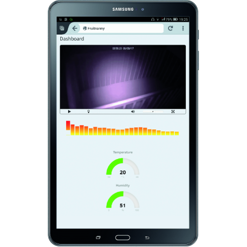
Fig. 11
The colors of the red, yellow or green temperature indicators give an indication of how comfortable or not the rest environment for our baby is. At this point, if you have had the patience and constancy to get to conclude the project, there should be no more doubts about the differences in functionality and destination between a device with a microcontroller and a computer with an operating system. What we have just presented is, however, a project of integration between microcontrollers and microcomputers. Both the Pi Camera and the DHT sensor are equipped with microcontrollers that acquire images and data and communicate with the microcomputer using digital protocols. For those wishing to deepen the functionality of the packages used in this project, the best source of information is definitely the web, as well as some good books. We can only wish our baby dreams of gold and good luck to those who want to try their hand at carrying out this project.
From openstore
IR camera with 2 IR LED 3W for Raspberry Pi
Board with DHT11 temperature and humidity sensor
