
By making use Raspberry Pi, we created an easy to build 3D scanner to be used for the acquisition of three-dimensional models via a video camera and a laser
3D printing keeps on establishing itself, mostly thanks to the availability of more user-friendly 3D printers and price drops. Those who use a 3D printer do it both for printing a original models of their work (such as for example, the scale model of a building or the replica of mechanic particulars), and to print items modelled from others for which STL files are often available. In order to reproduce an item – if the STL is not available – you will have to create it, and there are two ways to do it: either using a 3D modelling tool or by acquiring a 3D drawing for the item, by means of a specific three-dimensional scanner. 3D Scanners are used in various fields, going from industry (for the copy of an object, starting from a model, a mould or an item to be replicated) to medicine (it is used, for example, by dental technicians so to scan the mouth’s cast and pilot CNC machines or 3D printers with which to build dental crowns and tooth caps, but also for the modelling of orthopedic implants). The scanner is also needed to acquire an object’s model and to remotely send it, where a 3D printer may replicate it; this is needed, for example, if it is necessary to send a sample from the other side of the world, but you cannot wait for the times needed by the couriers.
3D scanners are also used in order to acquire three-dimensional models of sculptures, archaeological finds, etc.
A 3D scanner is a very sophisticated equipment, and a decidedly expensive one, not really within everyone’s means. Luckily, the technology it is based on may be replicated – even with a limited expenditure – as we will show you in this article, in which we will propose the construction of a scanner based on Raspberry Pi 2, the well-known prototypation board.
TECHNICAL FEATURES
- 5 megapixel video camera
- Colour scan
- Up to 6,400 steps per plate rotation
- 0.25 mm resolution
- Scannable volume 200 X 200 X 150 mm
- Assisted calibration
- Power supply’s voltage: 12 Vcc / 700 mA
The technology
Nowadays there are different solutions for carrying out a scan: structured light, laser and video camera as for visible light or IR, video camera only. The structured light technology offers excellent results but involves a complexity and costs that not always may be acceptable ones, while the ones that proved to be the most affordable ones are the laser technology plus video camera and the video camera one: in the first one, that is the one you will see applied to the project in this article, one or two lasers draw a vertical line on the area to be scanned, and a video camera shoots the surface lighted by the laser. On the other hand, the technology using only the video camera is based on acquiring a certain number of frames “shot” at each turn carried out by the object to be scanned on a turning plate: the greater the number of frames per turn (the camera’s resolution being equal), the better the scan’s sharpness. A powerful software will then process the pictures, it will recognize the common points and will reattach them together as if they were photographs of the same object from various points of view, and until the reconstruction of a three-dimensional model on the PC screen (that is then converted in STL) is completed. With respect to the video camera only technology, the one using the laser plus the video camera has the following advantages:
- a greater image contrast, since the shootings on the video camera are obtained from the laser’s light reflection, therefore the image acquired is a good one, even with little light;
- it allows a greater detail, due to the fact that it does not analyze a single frame, but a very luminous line on the object’s surface, therefore it allows to detect even a slight roughness on the surface, and to supply a better image of the shape variations;
- it manages to acquire a scan even for items having an uniform surface and form;
- it does not require the application of a background to the scene to be shot;
- it requires less calculation power for the construction of a three-dimensional model.
On the other hand, the solution has some inconveniences:
- the laser’s calibration is a critical factor for the outcome, therefore if the scanner’s structure is prone to get flexed, the centering and the verticality on the rotating plane of the light line may move, with a consequent misalingment and the absence of overlapping among the surfaces detected by the single laser;
- in the case a single laser is used, an absent or wrong calibration may determine deformations in the model resulting from the scan;
- the settings concerning the video camera’s position with respect to the plane’s rotation centre and the correct calibration on the horizontal plane are critical for the attainment of a correct scan;
- if a horizontal surface of the object is found at a height that is greater than the centre of the video camera’s optical system, it is not acquired;
- horizontal surfaces inside the object (as an example, the bottom of a glass) cannot be hit by the laser beam and therefore are not acquired;
- if the object has a surface having different reflection coefficients, the video camera – since it has set a single threshold value – will be blinded in the points in which the laser is reflected the most and will see darkness in the points in which the laser is absorbed;
- with difficulty the STL file of the scanned item will be suitable to be directly used for the printing, therefore the scan will have to be processed by means of 3D processing software.
As for the technique with the video camera only, the advantages are:
- it does not require lasers, nor their calibration, it is therefore insensitive to the lasers’ positioning and alignment;
- the hardware is much simpler;
- it better shoots the surfaces having different light reflection coefficients.
At the same time, it must be said that the software for this kind of scanners is typically born for systems that consider the rotation of the video camera around the object, and not of the item around its axis, therefore:
- a background is needed in order to avoid that the original background (that is a fixed one) is framed as a reference; the white colour seems to be the most suitable one, since it diffuses the light. The part under the scanner’s plate must also be covered;
- a good lighting of the object to be scanned is required;
- it is not suitable for objects having a black surface, or a very reflective one;
- it must be avoided that the object’s shadows are shown in a too pronounced way, since they would remain fixed and the program would understand that the camera is not moving;
- in order to help the scanner, it is needed to put some coloured references on the plate (or on the item, but there it would cover some details), so that they are taken as landmarks; since they are moving, the program will think that it has been the camera to move;
- in the photographs, the object must be shot as a close-up, therefore if it is a small one you need to draw the camera nearer, possibly drawing the landmarks to the centre;
- the photographs have to be shot with a small angular displacement between one and the other;
- it is not suitable for objects having a too uniform surface, or a too uniform colour;
- it requires an image reconstruction software, that is often expensive and a demanding one from the point of view of the hardware resources required from the computer on which to execute the frame processing.
Ultimately, there is no technique being better than the other one, but each one is more indicated for a certain kind of objects to be shot, and for certain scan conditions.
Our scanner
This being said, we may move on to talk about our 3D scan approach, that consists in using a linear laser, that is, one capable of drawing a vertical line having a constant luminous intensity, and in shooting the images that have been determined by the light’s reflection on the object’s surface (that in this case is rotated) by means of a video camera; at each rotation degree (or fraction) corresponds a frame that is digitized and sent to a program capable of processing the surface of the scanned object. Usually, in these systems two lasers (tilted with respect to each other) are used, and the video camera is placed between the two. Our scanner is born out of an elaboration of the PiClop, an open project composed of a mechanics (whose parts to be 3D printed may be downloaded from thingiverse ) and of an electronics formed of the Raspberry Pi 2 board and its video camera; PiClop, as implied by the name, is a free interpretation, based on Ciclop’s Raspberry Pi 2 , a 3D commercial laser scanner and a video camera, supplied with a rotating plate. Even Ciclop (though it is commercialized) is a scanner having an open source information material. Our scanner differs from PiClop since we substituted Raspberry Pi’s video camera with one supplied with an adjustable optics, in addition to the original circuit that has been substituted with one of our shields for the management of the stepper motor (NEMA 17), that rotates the plate and the lasers. We preferred a video camera having an adjustable lens so to optimise the focus of the object, since we realized that the original one in the Raspberry Pi has a focus distance that is greater than the one between the base and the rotating plate that hosts the object to be scanned. Being able to accurately regulate the focus, we are able to obtain the best definition in the calibration stage, before starting the scan. The video camera is a 5MP IR one for Raspberry Pi, having a 3.6 mm adjustable optics.
The said scanner connects to the Internet: the management of all the functions, as well as of the parameter settings occurs via LAN network, therefore it may also be carried out remotely, by means of whatever computer. For the occasion, Raspberry Pi (it must be version 2) will have an image of the operating system with the dedicated management and control software (FreeLSS) installed (on the SD-Card), it is capable of generating files in the following formats: PLY – Colored Point Cloud, XYZ – Comma Delimited 3D Point Cloud, STL – 3D Triangle Mesh. The software implements a web interface, by means of which it is possible to operate with the scanner, that is to say, to carry out the settings and the acquisitions. For each acquisition a file is generated. FreeLSS implements:
- real-time scan preview;
- assisted calibration;
- two-lasers mode is supported;
- up to 6,400 steps per plate rotation;
- Still Mode and Video Mode camera are supported;
- parameter settings as for the image processing;
- the possibility to obtain partial images, so to carry out the debug in the case the scan does not succeed;
- the manual movement of the rotating plate is supported.
Circuit diagram
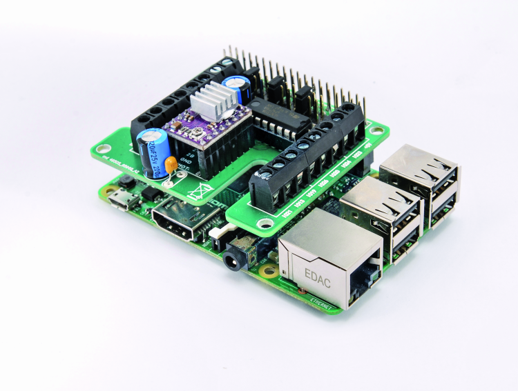
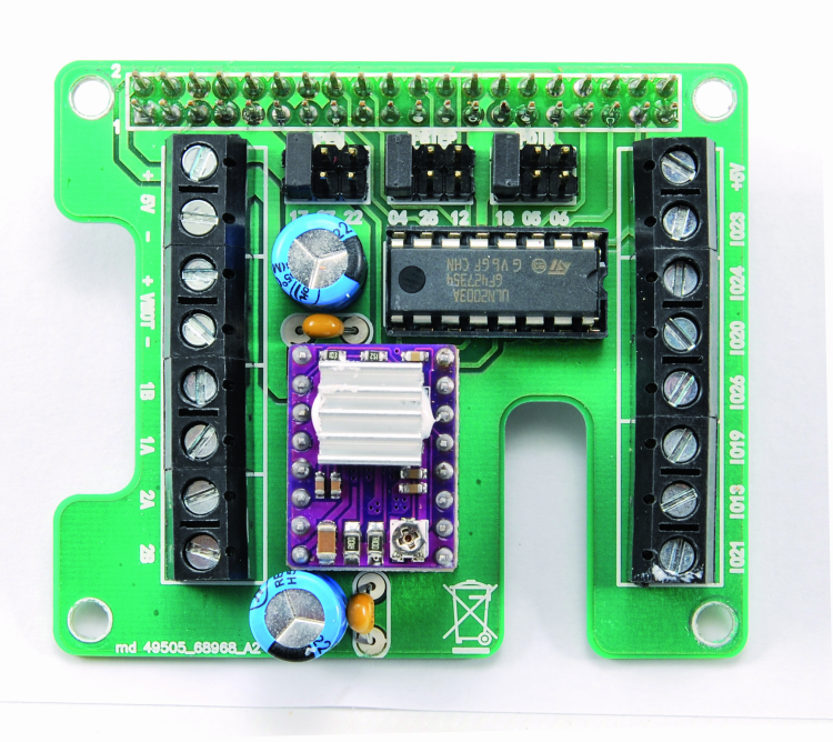
As a first thing, let’s give a look at the scanner’s electronics, that is based on Raspberry Pi and on the shield; the latter contains a driver for stepper motors that is based on Texas Instruments’ DRV8825 integrated circuit, that is one of Open Electronics modules (cod. DRV8825), in addition to a line-driver ULN2003 (U1), that is used in order to power the linear lasers as a consequence of a command from Raspberry Pi’s GPIO lines, that have been configured as outputs for the purpose. Please notice that – as regards the U1 – we make all the seven internal Darlington open-collectors available, even though it’s only two we are using; as for the other ones you may manage them at leisure. You will have to adjust the settings during the configuration, according to what we will explain later.
The driver (U2) allows to set the driveshaft’s direction of rotation and the number of degrees that the motor’s rotor has to do at the receiving of each command; in other words, we may decide if, when we give a command pulse, the module has to make the driveshaft rotate one step by one, or by 1/2, 1/4, 1/8, 1/16 or 1/32, depending on the desired accuracy. Actually, we set the functioning at a 1/32 of a step, by posing the pins MS1, MS2 and MS3 at the logical 1, so to obtain the greatest movement accuracy.
Raspberry Pi 2 commands the U2 driver, by setting the logical state of the /STEP, EN and DIR lines; it sends the pulses that determine the advancement of a step at the time in the rotation of the driveshaft to the first one (managed via one among IO04, IO12 or IO25, freely chosen), while DIR (IO05, IO06 or IO18) is defined from time to time, depending on the fact you want to obtain a clockwise or counterclockwise rotation. EN (IO17, IO22 or IO27) is needed so to enable or disable the module. In order to command the rotation of a driveshaft’s step, the microcontroller poses EN at a high logical level and it keeps it in this condition, then it sets DIR at logical 1 if the rotation has to occur in counterclockwise direction or at logical zero for the clockwise direction (always keeping this logical condition as well) and finally it supplies a low level pulse to the /STEP line; once this has been done, it brings both EN and DIR to idle state. If the advancement has to be for more than one consecutive step, while EN and DIR are active the microcontroller sends the required pulse sequence to /STEP.
Please remember that the motor moves, for each pulse that Raspberry Pi 2 sends on /STEP, accordingly to the settings of MS1, MS2, MS3; in our case 32 of them are needed in order to make a step.
Please notice that for each driver’s command line we have considered the possibility to choose – by means of bridges – among three GPIO lines; this has been done so to give you the possibility to mount more than one shield on Raspberry Pi 2 and thus to manage other applications, in addition to the scanner, and also to use the shield as general controller for other usages, and maybe to command two or three stepper motors (in that case it is almost inevitable to use different GPIOs for the various boards). Once the shield has been mounted, please place the jumpers as you please and write it down, since you will then have to set the GPIO lines in the software, accordingly to what will be explained later.
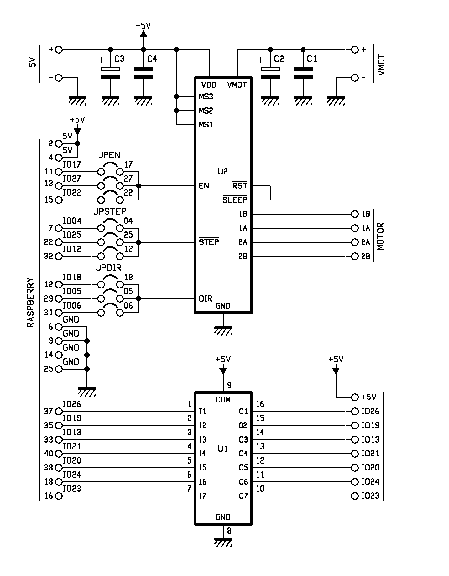
This being said, we will go on by claiming that each driver is composed of a double H-bridge, governed by an electronics that allows to set the electromagnetic field’s direction of rotation and therefore the one of the stepper motor’s driveshaft. Each time that a pulse comes on the STEP pin at a high level (the minimal tolerable duration is 1 µs) – unless there are different settings – the 1A, 1B, 2A and 2B outputs supply the pulses used in order to command if the motor’s rotor will move by a step or a fraction of it. We will end the overview concerning the drivers by talking about the /SLEEP pin, that activates the sleep mode (active logic and drivers turned off) and about RST, that resets the controller that governs the drivers and that sets the motor’s command outputs (1A, 1B, 2A, 2B) to a logical zero, even if STEP continues to receive pulses. In our application, RST and SLEEP are deactivated, since SLEEP has an internal pull-up resistor and by joining them they are both at 1.
The shield is prearranged in order to receive two distinct power sources: VMOT is applied to the specific terminal box (and it is the 12 volt DC one for the motor), while 5V (mentioned on Raspberry Pi 2’s expansion connector) powers the driver’s logic and the ULN2003 line-driver.
Mechanics and optics
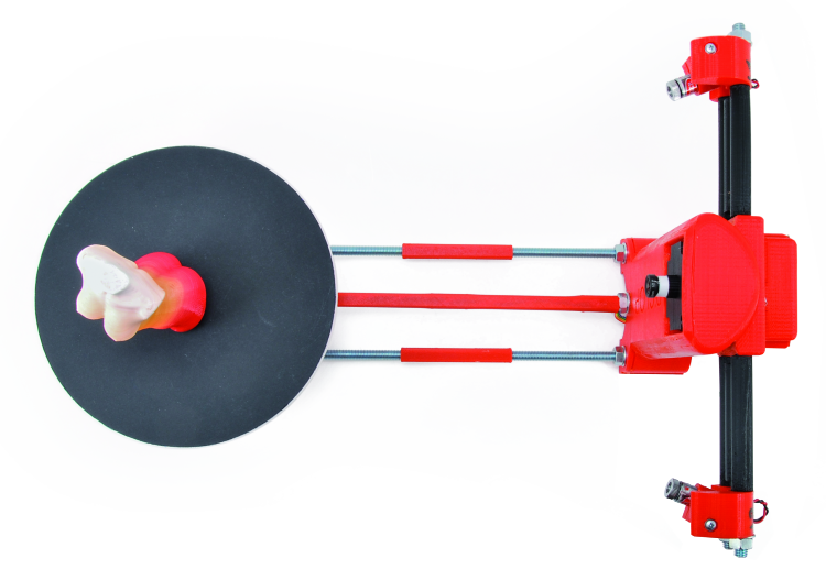
We will now move on to talk about the scanner’s mechanical part, that is the set of the plastic printed parts (for example, as created by our 3Drag) and assembled by means of iron threaded rods and bolts; the main blocks are the base (that contains the electronics and the video camera at the center and the two linear lasers at the sides), and the plate that supports the object: it is a turning one on a bushing that has been secured to a plastic support that is connected to the base by means of threaded rods. The plate may be obtained from a plexiglass or forex disk (a 4 mm thick one) but it may also be in PLA and therefore a printed one; after having applied a black cover sheet, please locate its center and highlight it as a dot made by means of a permanent marker.
The linear lasers are Class 3A, red light semiconductor ones (with a wavelength of 650 nm) of the 2510-LASER5MWLINEA kind from Open store; each one of them develops an optical power of 3 mW and requires a power source having a DC voltage of 4÷6 V (it absorbs 280 mA). The laser integrates a collimating aspheric lens in order to direct the light to a single point, that is then transformed into a line thanks to a cylindrical acrylic lens, placed at the exit of the laser ray, so to create a light beam having a triangular section with an opening of about 45°.
How it works
In order to acquire the object’s shape, our system executes a superficial analysis of the same, by rotating it on a plate by a degree (or a fraction of it) at a time, while the light of a linear laser is directed towards it; the laser projects a vertical line that covers the whole height of the object to be scanned and the reflected light reaches a video camera that acquires the resulting images and sends them to the dedicated software. In order to acquire all the needed information, the object is rotated by an angle, chosen at your discretion, even though usually a complete rotation (360°) is carried out. The program allows to establish the number of steps that the NEMA 17 motor has to carry out in order to complete a whole revolution (360°) and up to 6,400; our stepper motor is a 200 steps per revolution one, and when driven by the shield, it carries out a step with every 32 pulses on STEP that come from Raspberry Pi 2; therefore 200 steps multiplied by 32 gives 6,400.
The linear laser beams are inclined between them by 60° on the horizontal plane, therefore the video camera, since it is centered with respect to the two lasers, is placed with a 30° angle with respect to the beam of each one of them.
The scanner has to operate in an environment that must not be excessively well-lighted, so that there is a clear contrast between the zone hit by each laser’s line and the surface of the object to be scanned.
When the scan is started, Raspberry Pi 2 will begin to acquire the images (frame) supplied by the video camera, with a periodicity set by the software: the default value is 800 per whole revolution of the plate (and therefore, of the object), but we also tried to operate with 2,000 frames per revolution.
The need to use a second laser arises when you need to scan, for example, a cube: in this case, in fact, when using a single laser only, some grey areas are created because of the misalignment (that is to say, the different angle with which the two elements address the object to be scanned) between the video camera and the laser.

In this specific case, since the two are not on the same axis, during the rotation there are some zones in which the ray is darkened by one of the faces and it does not reach the video camera, thus preventing the perception of the reflected ray and therefore determining some “holes” in the model acquired. If we add a second laser, tilted by 30 degrees in the counterclockwise direction, the grey areas disappear: in fact, when the object rotates and goes beyond the critical angle of the first laser, the grey area is scanned by means of the second one. As for the acquisition of objects that do not possess faces such as to hide the laser’s line from the eye of the video camera, it is possible to use only one laser for the scan.
Let’s see therefore how the acquisition is carried out: for each frame, the reflection of the laser’s line (that is vertical and represents a very small slice of the surface) is taken into consideration; at each rotation therefore a frame is acquired, the latter has a lighted segment that falls each time in a position that is always different, until the desired surface is completed. For each frame, Raspberry Pi 2 analyzes the lighted zone, and discards the rest of the image, that is used just for the purpose of verifying the correct sequence for queueing the slices; by putting the slices together the image is reconstructed.
The software
Let’s move on to talk about the program that runs in Raspberry Pi 2 under the Raspbian operating system and that is named FreeLSS, as previously anticipated: it may be downloaded from the https://github.com/hairu/freelss website. In order to access it from the network, please open the browser and write the IP address assigned by Raspberry Pi to it, then press Return; once the network connection has been established, the main screen will appear: we will now describe its various sections.
SCAN
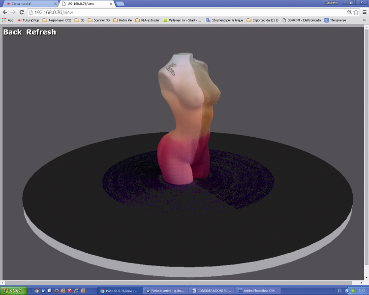
In this section the scan is executed. By clicking on “Start Scan” from the SCAN menu the 3D scan of the object is started. The scan preview will appear on the monitor, as well as the file save in the desired format, the first one will be carried out with a resolution that is inferior to the one that will be set for the actual scan. If we approve the preview, we may start the download.
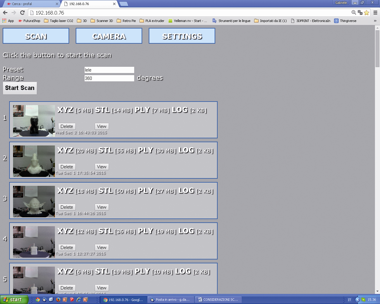
CAMERA
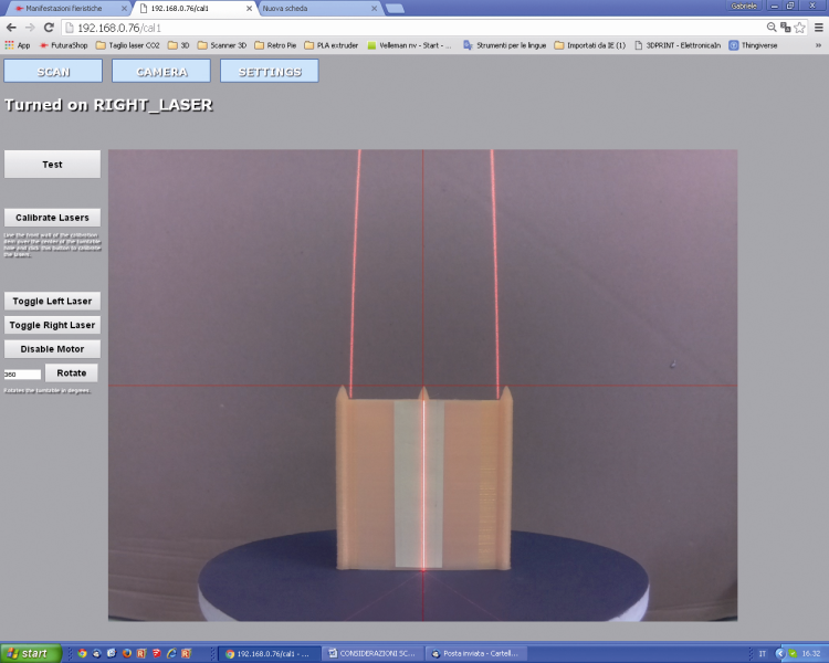
Here (first figure) the parameters of the video camera are set and the lasers are calibrated. By clicking on the “Test” button a sample acquisition is carried out, it allows to verify the collimation of the two laser lines (only on a plain surface, being orthogonal to the plane) and if the value for the “Laser Threshold” field is a correct one.

The line must prove to be as uniform as possible (not serrated and/or jagged). In figure you may see what happens when the value set for the Laser Threshold is too low;

Figure shows what happens when we set an excessively high one.

Finally, in follow figure you may see how the image will appear if the Laser Threshold value is a correct one. In the same section, by clicking on the “Calibrate Laser” button it is possible to access the laser calibration, that may be carried out only in the 5MP still or 5MP video modes.

Once the lasers have been calibrated, the small yellow and green crosses (they may be seen in the test) will overlap. If the lasers are not calibrated, the crosses will not appear as overlapping or they are only partially doing it.

As for the commands available in the calibration section:
- by clicking on the “Toggle Left Laser” button the left laser is activated/deactivated;
- by clicking on the “Toggle Right Laser” button the right laser is activated/deactivated;
- the “Disable Motor” button disables the motor that rotates the table and therefore it stops the rotation, if it is underway;
- the “Rotate” button starts the rotation of the rotating plate by an angle (measured in sexagesimal degrees) that is equal to the value we set in the next field.
SETTINGS
In this section it is possible to set some Preset, custom values and to save them at leisure, that is to say, to execute the settings of all the operating parameters described as follows.

The Laser Selection defines the laser that will be used during the scan: the left one (SX), the right one (DX) or both.
The Camera Mode sets the video camera’s shooting mode (the Video mode is faster, while the Still one allows for a higher scan quality). The values are predefined in the specific drop-down menu, it is possible to access it by clicking on it, they correspond to as many modes: 0.3 MP (640×480 video mode); 1.2 MP (1.280×960 video mode); 1.9 MP (1.600×1.200 video mode); 5 MP (2.592×1.944 video mode); 5 MP (2.592×1.944 still mode).
Frames Per Revolution indicates the number of frames shot during the scan (800 is the default value). A greater number of “shots” per revolution determines a more accurate scan and also an increase as for the scan times and for the size of the generated file.
The Laser Threshold defines the brightness value that the pixel must have (when it is hit by the reflected laser’s light) in order to be detected; if the object has a surface having different reflection coefficients (and since a single threshold value has been set) the video camera will be blinded in the points in which the laser is reflected the most, while other dots will turn out to be dark or the video camera will lose the dots in which the laser beam is absorbed (because of the colour or the material’s porosity). In the first case the reflection will generate a cloud of dots scattered in the space in front of the zone hit by the laser beam, while in the second one a “hole” will remain in the obtained module. If the value is too low the video camera will be more sensitive, but the risk is that a cloud of dots that “dirties” the object is created around the point hit by the laser (the model will then have to undergo a “focused removal” of the unnecessary dots by means of a 3D processing software such as, for example, MeshLab) while if it is too high the video camera will risk to not “see” or to see only partially the laser beam on the object’s surface. In order to verify if the set value is a good one or not please use the “Test” function: after having placed the object on the plate, please click on the “Test” button; after a few seconds an image (.png) will be returned, it shows how the video camera sees the laser beam(s) on the object’s surface .
If the line(s) turn(s) out to be discontinuous (dotted) we need to lower the value, while if they turn out to be jagged or very confused (they have an aura) we need to raise it.
Ground Plane Height defines the scanning plane’s height under which the scanner may not carry out the scan.
Stability Delay defines the time (expressed in microseconds) that the video camera has to wait, after the plane’s rotation, before shooting another picture.
Max Laser Width defines the maximum width of the laser’s line (expressed in pixels).
Min Laser Width defines the minimum width of the laser’s line (expressed in pixels).
Generate PLY File converts the scan in a PLY cloud of dots.
PLY Data Format defines the PLY file’s format (Binary or ASCII).
Generate STL File supplies the scan in a .stl file.
Generate XYZ File converts the scan in a XYZ cloud of dots.
Separate the Lasers Calibration is a debug option, used in order to separate the images obtained by the two lasers, and distinguishes them by using different colours (it requires PLY).
Enable Burst Mode enables the video camera’s burst mode, during the still mode acquisition.
Create Base for Object adds a flat base to the object, so to simplify the 3D printing.
Start and regulations
Let’s see now how to work with our scanner, but with a premise: the calibration function requires the creation of a “calibration object” that you will have to obtain by means of 3D printing (the file is calibration_item.stl and you may download it from the magazine’s website). Once the object has been created, please connect Raspberry Pi 2 to a monitor (via a HDMI cable) and to the LAN (via a dedicated cable). Please power the shield with 12Vcc for the motor and with 5Vcc – 1 A for Raspberry Pi 2. We opted for a single 12Vcc power supply and used a DC/DC module in order to obtain the 5Vcc needed by Raspberry Pi. Once Raspbian has been booted, please type cd freelss/src from LXterminal and press Invio. After that please type sudo ./freelss and then press Invio: a video will appear, showing the following writing: “Running on port 80…”.
Now, please type the IP address assigned to Raspberry Pi 2 in the PC browser’s address bar. Please set the required hardware values (video camera/laser coordinates, Steps Per Revolution, pin board, etc.) from the SETTING/setup menu; in particular, before any operation you will have to define Raspberry Pi’s GPIO pins that have been assigned to the left (Left Laser Pin) and right (Right Laser Pin) lasers, in addition to those corresponding to the EN (Motor Enable Pin), STEP (Motor Step Pin) and DIR (Motor Direction Pin) lines of the shield’s U2 driver. In Raspberry Pi 2 – whose GPIO connector is of the extended kind and it supports more I/Os of the ones supported by the first Raspberry Pi – some GPIOs have been fixed at a hardware level and the extended ones have been mapped by means of a specific library. The FreeLSS software uses the wiringpi2 library, therefore the GPIOs that are connected to the ones to be typed in the web interface’s boxes are the corresponding ones in the WiringPi.
The lines have to be chosen in the interval that is considered by the shield, in the sense that if it may be connected – as for EN and by means of the JPEN jumper, to IO17, IO22 or IO27, then in the Motor Enable Pin you should only write 17, 22 or 27. As for the ULN2003’s outputs, the lasers have to be connected to the corresponding ones to the IOs that you want to specify in the screen view. Please refer to the table in figure.

If you want to connect a lamp so to light the scene, you will have to check the Enable Lighting box and to type the GPIO pin with which you will control the Lighting (what we just said is still valid) – by means of one of the ULN2003 free outputs – in the box below.
Once the settings have been selected, please click on the CAMERA button in the web interface so to see the monitor preview of what the camera shoots. Please regulate the video camera’s optics so that the object on the plate is being focused and tilt the video camera on the horizontal plane, so that the inferior dash found on the red centering cross corresponds to the plate’s centre of rotation. You will then have to put the calibration object on the plate (towards the centre) with the ends pointed upwards: the horizontal line must equally lean on all the three ends even during the rotation (if it is too high or too low, please modify the Camera Y value in Setup); if it doesn’t occur, it means that the video camera isn’t perfectly horizontal. The two pictures in figure help to clarify the concept.

In order to activate or deactivate the lasers, you will have to click on the “Toggle Left Laser” and “Toggle Right Laser” buttons.
The two laser lines must converge towards the centre of the rotating platform and be perfectly normal with respect to it; for the purpose it would be convenient to place the calibration object on the platform so that a face is exactly aligned with the plane’s centre of rotation. Please make sure that the laser beams perfectly overlap.
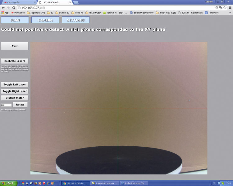
While in SETTINGS, please set the 5 MP (still mode 2592×1944) video camera’s shooting mode and enable both lasers (Both Lasers) by means of “Laser Selection”. Please save the settings and return to CAMERA, where you will have to click on Calibrate Laser; a few seconds after the system will inform about the occurred calibration (it may only be carried out in the 5MP still or 5MP video modes, otherwise the system will return an error). If you do not place any object on the rotating plate, the system will return the error message shown in figure , above the picture. Please put now the object to be scanned on the rotating plate.
Please click on the Test button, in order to verify if the Threshold value is a correct one. Please select the desired options while in SETTINGS, then move to SCAN and click on Start Scan, so to start the object scan: a preview of the real-time scan will appear on the monitor.
At the end of the operation a box will appear – with a miniature of the scanned object – from there it is possible to download the scan files in different formats.

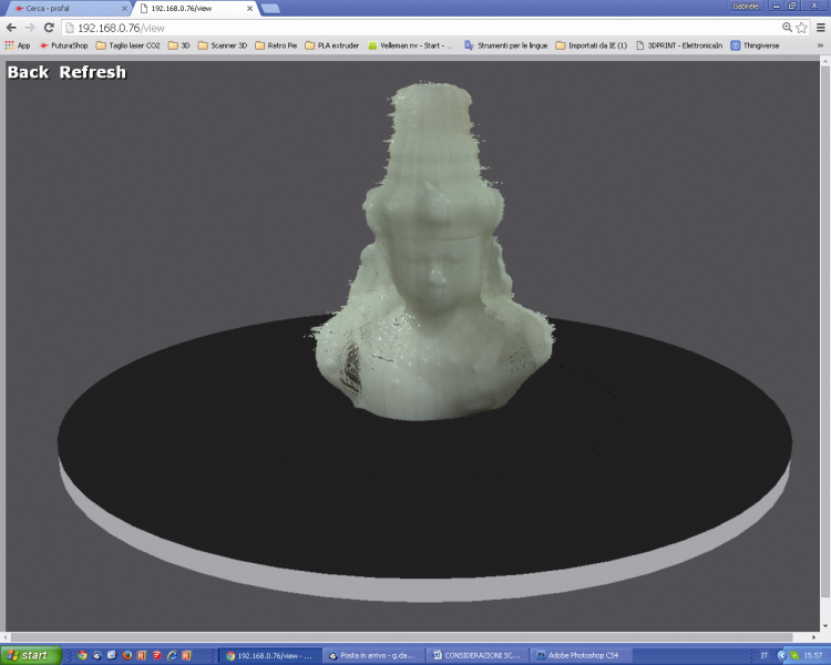
The object may be seen again in 3D format, by clicking on the View button or it may be deleted by clicking on the Delete button.
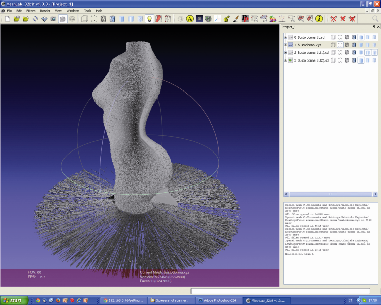
If the scan reached a successful ending it may be exported, so that it may be opened later on a PC via the repair software. This figure shows the XYZ file related to a scan imported in MeshLab. The object has to be “cleaned” and repaired since – please keep it in mind – in order to have the 3D models printed and therefore to generate their STL file, they have to be hermetic (without “holes”).
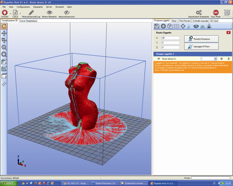
The downloaded files may not be immediately used for the printing, however, since they contain some errors: the figure shows the import in Repetier Host and the errors being highlighted;
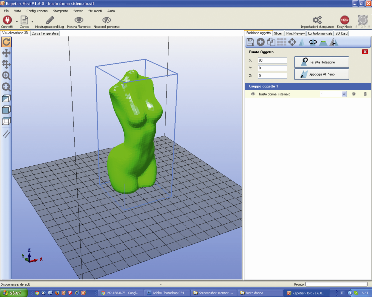
In figure shows the model as repaired and made hermetic.
Well, with this we have concluded; in the next installment we will see the scanner version with the video camera only.
3D scan systems
Nowadays it is possible to find both fixed scanners (that is to say, to be permanently mounted) and portable ones available for sale: the most renowned one is GoScan 3D, that is a manual scanner that has be pointed towards the objects while revolving around them so to acquire the whole surface; it is supplied with a self-positioning system that compensates the errors due to the fact that the hand is not always stable and that, by rotating, the scanner’s height it changes. As for the scan it uses lasers and a video camera and it has a scan accuracy of 0.1 mm (the resolution is 0.2 mm).
Many scanners work just like GoScan 3D.
Another solution – and certainly a very affordable one – for carrying out 3D scans consists in using devices that are born for other purposes, such as Microsoft Kinect or equivalent ones (for example, Asus Xtion Pro) for modern gaming consoles, capable of detecting the player’s movements and of sending them to the system so that he may be able to command his own avatar in a videogame or to transmit the movements to an interactive program. Kinect works like this: the infrared projector projects a specific pattern, made of equidistant dots. By analyzing the image obtained by means of the IR video camera, Kinect determines the the distances among the various points, and from them it acquires the distance and the inclination of the lighted object. Since the IR beam starts from a restricted area and it gradually broadens as the distance increases (it is more or less conical…), where the dots prove to be very close among each other, it means that the object is close to the sensor; vice versa, if the distance among the dots is a remarkable one, it means that the object is farther away. In order to understand this better, imagine to place a polka dot blanket on a surface of an object: it is possible to identify the shape of the said item on the basis of how the dots are arranged, as the blanket gradually wraps the item itself. In order to acquire with Kinect and similar devices, you need a Personal Computer and the ReconstructMe software with the appropriate software for the sensor that has been used. A program that may be an alternative to ReconstructMe is Kscan3D, but in this case the Trial version does not allow to save the model, therefore it would not allow you to reach the printing stage (it is used only to evaluate its functions).
In order to carry out the scan via Kinect and similar devices the object must be placed before it on plate or a rotating stool, after that please place Kinect on a stable tripod.
In addition to these techniques, there is a laser and video camera scan (the lasers are two) of the rotating object, that is the subject of this article.
A technology that produces excellent results is – on the other hand – given by the fusion of stereoscopic and photometric data that, for example, is implemented on the Fuel3D Scanify scanner; there are still two lasers, but the video camera is a stereoscopic one and is calibrated on them. During the scan it supplies two kinds of data: 3D images and corresponding photometric features; the whole occurs in less than a tenth of a second. Afterwards, it processes the two pieces of data and compares them, so to have a very high accuracy. Such a system is ideal in order to acquire human faces, cloth weaves or natural elements such as flowers and plants.
There is also the valued technique of the structured light scanning: a scan projects a known light diagram – typically having horizontal and vertical parallel lines – on the surface to be acquired. The deformation induced by the object’s surface is acquired by means of the video camera and it is taken advantage of, for the purpose of the calculation of the three-dimensional coordinates. Such systems are named full-field systems since for every sensitive dot of the acquisition system’s CCD or CMOS, three dots (x,y,z) in the space are acquired. Such a system allows the digitization of many dots at a time: according to the video camera’s resolution we may reach even different hundreds of thousands of dots.

By projecting a narrow light band on a three-dimensionl object a luminous line is obtained: from different observation points from the projector, it appears as distorted and it may be used for a correct geometric reconstruction of the lighted surface’s shape (luminous section). “Triangulation” is the name given to the procedure with which the shape of the object hit is reconstructed. A faster and more versatile method is the projection of luminous diagrams that consist in many lines at a single time, or of arbitrary luminous fringes. The light strips may be generated by means of interference of laser sources or via projection method. In the first case, two planar light sources are let to interfere between each other: the result is the creation of regular and equidistant lines. The size of the fringes may be modified by changing the angle between the two beams. This method allows to generate a very accurate pattern that has a great depth, but it is an expensive one, it suffers from reflection and from the typical flaws of the laser sources (speckles). The projection method takes advantage of means that generate incoherent light, that is to say the projectors; if on a side some small discontinuities are found in the scan (due to the pixel edges that compose the picture), on the other one they may be diminished by lens focusing. In both cases, the picture that is gradually created on the lighted surface is acquired by means of one or more video cameras.
From Openstore
IR camera with 2 IR LED 3W for Raspberry Pi
5mW red laser module Line – 650nm

[…] An open source 3D Scanner made with Raspberry Pi | Open … – Open Source Electronics is the brainchild of a world leader in hobby electronics Futura Group srl. Open Source Electronics is devoted to support development, hacking … […]
[…] An open source 3D Scanner made with Raspberry Pi | Open … – Open Source Electronics is the brainchild of a world leader in hobby electronics Futura Group srl. Open Source Electronics is devoted to support development, hacking … […]
thanks your post.
but i have some q.
What is VDD Pin on 8825?
https://www.google.it/search?q=8825+driver+pinout&source=lnms&tbm=isch&sa=X&ved=0ahUKEwiV3YGirt3SAhWK0xoKHa_OCx0Q_AUIBigB&biw=1920&bih=950
I have seen it.
but i q because in schematic, VDD connect to U2.
– what it’s mean VDD connect to U2?
So, 8825 Driver don’t need to connect VDD, only VMOT ? am i right?
I think the circuit configuration is complete.
I want build this project on RPi3. so I follow the doc(https://github.com/bqlabs/opencv/wiki/Build) to install customizing OpenCV.
but It’s not work for me.
Can I ask your favor?
[…] Available in our store the shield used with Raspberry Pi to make a 3D scanner. […]