

Here we present a small, low cost single channel receiver, encoding MM53200 and HT-12, with code self-learning function. Decoding is achieved by means of a PIC microcontroller by Microchip, that deals even to the memorization of 5 codes and governs the relay output as well.
Features
– Number of outputs: 1
– Output: Monostable, Bistable
– Power Source: 12Vdc
– Absorption: 40 mA max.
– Memory: 10 remote controls
– Encoding: MM53200/HT12
The MM53200 encoding, that owes its name to the integrated encoder/decoder from the then National Semiconductors, is probably the oldest to be used in radio and infrared transmissions that are implemented in remote controls; and precisely the diffusion and the success obtained drove other builders, such as UMC, to develop “clones” like UM3750 and (at a later stage) UM86409 (capable of operating even at 5÷6 volt). Despite the limited number of combinations (only 4096) the MM53200 encoding offers many qualities, one of them being the possibility of controlling the encoding pins with binary logic levels or simple binary dip-switches, and the fact that both the encoding function and the decoding function are carried out by a single integrated circuit: depending on the settings of a dedicated pin (no. 15), the MM53200 and its clones may operate as encoders or decoders (two pins are there to receive or transmit the codes).
As much as it can be considered limited and unsafe today (in comparison to the rolling-code systems or to the more dated Motorola MC14502x encoding), since it has only 4.096 combinations, the MM53200 encoding is still much used, and particularly for door/gate openers; thus, a product from Holtek, named HT-12, was added to the traditional encoders/decoders, and it is fully compatible.
To meet the requests of those who have to maintain remote controls based on type encoding, and specially for those who have different transmitters but can’t find anymore the receivers of a gate opener control unit, we thought to create e single channel receiver with a relay output, capable of identifying the standard MM53200 codes and to be coupled, by means of a simple procedure, to a maximum of five transmitters.
Our circuit stands as a candidate to substitute the existing receivers, decoding MM53200; and the availaility of the self-learning function allows to couple the existing transmitters with great ease, without having to worry about the clock frequency of the encoder.
We have in fact to remember that the MM53200 transmits data strings that are timed by the clock generated by an internal oscillator, whose work frequency depends on the R/C network connected between the pin 13, the power source positive and the ground; in a traditional system with a receiver depending on MM53200, UM86409 or UM3750, the clock network has to determine a frequency that is the same of the one placed on the transmitter encoder, otherwise, even if setting the coding inputs in the same way (that is to say, the code dip-switches) the decoder will not be able to identify the incoming strings.
In our receiver, decoding and code coupling (as regards the five transmitters) are entrusted to a microcontroller, whose firmware is capable of adapting itself to the clock frequency of the encoder placed on the transmitter (provided that it works at 1,7 KHz), to synchronize with it and then to extract the code to memorize it, that is to say, to analyze it so to command the relay output.
Electric Diagram

The electric circuit of our receiver is really essential, thanks to the microcontroller, that alone carries out the task of the decoder (but has a case that is half as big as the one of MM53200) and of code memory, in addition to not needing dip-switch and clock network.
In the RF section we use a receiving module by Aurel, at 433,92 MHz, capable of receiving transmissions in OOK (On Off Key) amplitude modulation. In particular, we use AC-RX2(U3), an hybrid and very cheap module that at the same time is reliable, adequately selective and sensitive enough. The U2 module contains the radio part of the circuit and is a specific Aurel receiver, fitted with an antenna signal amplifier (granting as much as -106 dB), super regenerative stage tuning, tuned at 433,92 MHz by means of a compensator that has been calibrated by the manufacturer and equipped with a RF filter (the filter is needed to improve the selectivity, that is not high in the super regenerative units) and amplitude demodulator. The module package is completed with a comparator square of the digital signal (at TTL level) coming from pin 14 and with a LF amplifier of the signal coming from the AM demodulator.
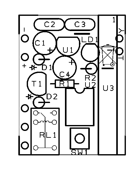

Both the receiver and the microcontroller have to be powered at 5V, a voltage obtained by means of the U1 regulator, a 78L05 in TO-92 format that obtains its 5 volts by starting from a 12V input voltage (applied to the PWR platform and needed to power the relay) at well stabilized 5V. The C1-C2 filter, placed at the stabiliser intake, removes possible inconveniences; the C3-C4 filter (at the stabiliser outlet), on the other hand, removes possible residual noises. The D1 diode, always present in our projects, protects the circuit from possible accidental inversions in the power supply voltage. As already hinted, this project has been created with a PIC12F675, a microcontroller in 8 pin DIL format, by Microchip. This integrated circuit has the availability of 6 I/O ports, but only 5 of these have been used. Let’s start from the GP0 line (pin 7), to which the LD1 LED is connected; the latter communicates with the different operating states of the system, such as the identification of MM53200 codes, their memorization and erasure, and much more. The SW1 microswitch is connected to the GP1 line, and it starts the call for the memorization and erasure routines of the codes; on such line an internal pull-up resistance is active, thus forcing GP1 to the high state when SW1 is not pressed. The GP2 line represents the input for the serial data string, obtained from the demodulation operated by the RF module (U3). The PIC doesn’t require quartz to synchronize the clock, since we’re using the internal oscillator at 4MHz, calibrated by the same manufacturer, and having a 1% accuracy. The usage of the internal oscillator, in addition to further reducing the circuit encumbrance, frees GP5 and GP4, the two output lines here employed for the creation of the bistable (GP5) and monostable (GP4) outputs.
To decide which type of command has to receive the output relay, a jumper to be weld has been designed, to be realized on the printed circuit board. To activate the bistable mode the central contact on B has to be closed, while to obtain the monostable operation (“impulsive”) the central contact has to be closed on M. The thus selected output drives, by means of the R1 resistance, the base of a BC547 mounted as a common emitter, whose collector supplies the coil of the RL1 miniature relay. In parallel to the coil the classic diode is found, and it is needed, at the transistor’s interdiction, to turn off the peak of reverse voltage that the same coil tends to generate as a reaction to the interruption of the current, following the well known Lenz’s law.
Please notice that in monostable mode the output is not timed as one would expect, thus it returns to sleep state once the button is released.
The firmware
The source code has been compiled in PIC BASIC PRO language.
'****************************************************************
'*  Author  : Alessandro Sottocornola                           *
'****************************************************************

INCLUDE "modedefs.bas"


'************************** D E F .    R E G I S T R O *************************
DEFINE OSC 4
DEFINE PULSIN_MAX 1350

ADCON0 = %00000000
OPTION_REG.7=0
CMCON0 =%00000111
ANSEL=%00000000
WPU=%00000010


'************************** D E F .    P I N    P I C **************************
symbol PULSANTE = GPIO.1
symbol LED = GPIO.0
symbol BIST = GPIO.5
symbol MONO = GPIO.4
SYMBOL RF = GPIO.2

INPUT RF
INPUT pulsante
OUTPUT MONO
OUTPUT BIST
OUTPUT LED

'************************* D E F .    V A R I A B I L I ************************
TX_MAX CON 10       'TX mem
TEMPO CON 40

CONTA VAR WORD
ERRORE VAR BYTE
I VAR BYTE
TRENO VAR WORD[25]
COD_A VAR BYTE
COD_B VAR BYTE
COD_1B var byte
COD_2B var byte
TROVATO VAR BIT
LOC VAR BYTE
RICEVUTO VAR BIT
CH VAR BYTE
TEMPO_RX VAR BYTE


TEMpO_RX=0
CONTA=0
TROVATO=0
RICEVUTO=0
errore=0


'********************************* I N I Z I O *********************************
CLEAR
eeprom 0,[255,255,255,255,255,255,255,255,255,255,255,255,255,255,255,255,255,255,255,255]
low led
low mono
low bist

'RESET COMPLETO SE PULSANTE PREMUTO ALL'AVVIO
IF pulsante=0 THEN
    high led
    loc=0
    for i=1 to TX_MAX
        write loc,255
        loc=loc+1
        write loc,255
        loc=loc+1
    next i
    pause 1000
    low led
endif

'Inizializzo facendo lampeggiare il LED
for i=1 to 10
    TOGGLE LED
    PAUSE 200
NEXT I
LOW LED

'*********************************** M A I N ***********************************
'Main che gestisce sia il bistabile che monostabile
MAIN:
    RICEVUTO=0
    gosub CONTROLLO_PULSANTE
    gosub CONTROLLO_RF
    if ricevuto=1 then
        high led
        pause 5
        GOSUB COMPRIMI_CODICE
        GOSUB CERCA_SENSORE
        IF TROVATO=1 THEN
            if tempo_rx=0 then
                'Monostabile
                high mono
                'Bistabile
                Toggle bist
            endif
            tempo_rx=TEMPO
        ENDIF
    endif
    if tempo_rx>0 then
        tempo_rx=tempo_rx-1
    endif
    if tempo_rx=0 then
        'Monostabile
        low mono
    endif
    low led
GOTO MAIN


'********************* C O N T R O L L O _ P U L S A N T E *********************
'Verifica la pressione del pulsante durante il funzionamento
CONTROLLO_PULSANTE:
    WHILE pulsante=0
        HIGH LED
        GOSUB CONTROLLO_RF
        IF RICEVUTO=1 THEN
            GOSUB COMPRIMI_CODICE
            LOC=0
            for I=1 TO TX_MAX
                read LOC,COD_1B
                LOC=LOC+1
                read LOC,COD_2B
                LOC=LOC+1
                IF COD_1B=255 AND COD_2B=255 THEN
                    LOC=LOC-2
                    WRITE LOC,COD_A
                    LOC=LOC+1
                    WRITE LOC,COD_b
                    WHILE PULSANTE=0
                        TOGGLE LED
                        PAUSE 50
                    WEND
                    I=TX_MAX
                ENDIF
            NEXT I
        ENDIF
    WEND
    LOW LED
RETURN


'*************************** C O N T R O L L O _ R F ***************************
'Decodifica il segnale RF ricevuto
CONTROLLO_RF:
    PULSIN RF,0,CONTA
    TRENO[0]=CONTA

    SELECT CASE CONTA
        CASE IS >1350
            RICEVUTO=0
        CASE IS >1075
            FOR I=1 TO 12
                PULSIN RF,1,CONTA
                IF CONTA<20 or CONTA>85 THEN
                    GOTO FINE
                ENDIF
                TRENO[I]=CONTA
            NEXT I
            GOSUB CODIFICA_MM53200
        CASE ELSE
            RICEVUTO=0
'    SEROUT SERIALE,T9600,[13,10]
'    FOR I=0 TO 12 step 1    'Visualizzo solo il dato identificativo del codice
'        SEROUT SERIALE,T9600,["-",#TRENO[I]]
'    NEXT I
FINE:
    END SELECT
RETURN


'************************** C E R C A _ S E N S O R E **************************
CERCA_SENSORE:
    'Controllo tra tutti i radiocomandi se c'è quello trasmesso
    LOC=0
    TRoVATO=0
    CH=0
    for I=1 TO TX_MAX
        CH=CH+1
        read LOC,COD_1B
        LOC=LOC+1
        read LOC,COD_2B
        LOC=LOC+1
'        SEROUT SERIALE,T9600,[13,10,#COD_A,"/",#COD_1B,"-",#COD_B,"/",#COD_2B]
        IF COD_A=COD_1B AND COD_B=COD_2B THEN
            TROVATO=1
            goto FINE_CERCA
        ELSE
            TROVATO=0
        ENDIF
    NEXT I
FINE_CERCA:
RETURN


'********************* C O D I F I C A _ M M 5 3 2 0 0 ************************
'Decodifica il segnale dei sensori MM53200 e invia su seriale il codice
'identificativo <02:..........>
CODIFICA_MM53200:
    ERRORE=0
    FOR I=1 TO 12
'        IF TRENO[I]<=28 or TRENO[I]>=80 THEN
'            ERRORE=1
'        ENDIF
'        IF TRENO[I]>=40 AND TRENO[I]<=58 THEN
'            ERRORE=1
'        ENDIF
'        IF TRENO[I]>28 AND TRENO[I]<40 THEN
'            TRENO[I]=0
'        ENDIF
'        IF TRENO[I]>58 AND TRENO[I]<80 THEN
'            TRENO[I]=1
'        ENDIF

        IF TRENO[I]<=20 or TRENO[I]>=85 THEN
            ERRORE=1
        ENDIF
        IF TRENO[I]>=45 AND TRENO[I]<=50 THEN
            ERRORE=1
        ENDIF
        IF TRENO[I]>20 AND TRENO[I]<45 THEN
            TRENO[I]=0
        ENDIF
        IF TRENO[I]>50 AND TRENO[I]<85 THEN
            TRENO[I]=1
        ENDIF
    NEXT I
    IF ERRORE=0 THEN
        RICEVUTO=1
    ELSE
        RICEVUTO=0
    ENDIF
RETURN

'********************** C O M P R I M I _ C O D I C E *************************
COMPRIMI_CODICE:
    COD_A=255
    COD_B=255
    COD_B.0=TRENO[1]
    COD_B.1=TRENO[2]
    COD_B.2=TRENO[3]
    COD_B.3=TRENO[4]
    COD_B.4=TRENO[5]
    COD_B.5=TRENO[6]
    COD_B.6=TRENO[7]
    COD_B.7=TRENO[8]
    COD_A.0=TRENO[9]
    COD_A.1=TRENO[10]
    COD_A.2=TRENO[11]
    COD_A.3=TRENO[12]
RETURN
Test and operation
The circuit, therefore, will immediately work once powered. For the test we’re gonna take one or more transmitters encoding MM53200 at 433 MHz. By powering, the device emits 5 flashes to indicate a correct start.
Learning procedure
Let’s see how to learn codes.
- Press the SW1 button and keep it pressed.
- The green LED (LD2) will turn on to indicate that we are in self-learning state and that from this moment we may transmit the code we wish to memorize.
- Press the remote control button that we wish to learn, and wait for the LED to flash quickly for three times; this is a sign that learning came to a positive ending and that the procedure (at least if you pressed and released SW1) is complete.
If the LED remains fixed, the memory is full or the transmitted code is invalid. Please notice that as for firmware’s operation, it is not admitted an encoding combination having all TX programmer’s lines at low level (you may not keep all dips switched ON).
Moreover, please notice that from the pressure of the SW1 button, you have 5 seconds at your disposal for the transmission and memorization of the code; by keeping SW1 pressed, instead of pressing and releasing it immediately, we may memorize up to 5 codes in sequence).
Memory Erasing Procedure
It is only possible to erase the whole memory and not just the remote control.
- Remove the device powering.
- Press the SW1 button and keep it pressed.
- Supply powering.
- The green LED will remain lit fixedly for 2 seconds, to indicate that the memory erasure happened.
- The green LED will emit 5 flashes to indicate that the erasure procedure is exiting and that the receiver is normally starting.
From the store

Muito Legal.
Dear. I got an error when compiling your program : “unable to varying fit” . It is the first time I use the compiler used . I need if you can help me understand what my error. From already thank you very much.
Gonzalo.
The code is witten in PicBasic Pro
salve, e possibile avere gentilmente il file .hex compilato ?
Here esche have been common control, or can have someone nebut emulator UMC UM3750, MM53200
Hi
I get a few errors trying to compile tih code
One of them is : unable to fit variable TRENO
Pleas could someone post a working code or .hex
Thanx
I have the same problem, seems that TRENO [25] is too big, I decrease is to 12 (which is the amount of codes and the compiler did not complain, I could not test it yet
Hi, we managed to do in PICBASIC HEX for circuits that allow us to PIC12F683 and auditioned and Boužel work.
Hi there, Any one has the hex file? Please send it to SouthCaliMan@yahoo.com.
Thanks. Dan
The code posted above is full of errors and the compiler cannot compile it, example the line IF TRENO[I]<=20 or TRENO[I]>=85 THEN ERRORE=1
I think it should be
IF TRENO[I]=20 or TRENO[I]=85 THEN ERRORE=1
Also the definition of the Treno array as word with 25 elements
TRENO VAR WORD[25] throws an error that says that the compiler cannot fit it.
Does anyone have the code corrected without errors?
on the Variable Definition, the TRENO VAR WORD[25] seems to be too big, the compiles complains that there is no space to fit TRENO, if I decrease that value to 12, then the compiler works fine, what could be wrong?
Dear friend I really very appreciate, your work is so good but, the given program is not working, I failed to convert it into hex,most website upload hex file too, if you have hex file why not upload it, because I am very strong in hardware but weak in software, if you will not upload hex then most visitor like me not visit,
Thanks
Dear friend I made the above switch but failed to make hex, please upload hex, you share most of knowledge about the circuit then why not upload hex file
Hi you can send the code compiled in hex format?