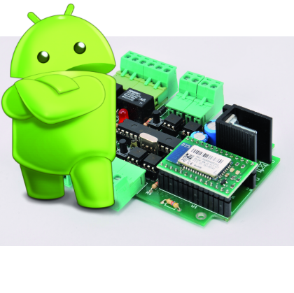
 With the new RN-42 Bluetooth module we created a Bluetooth remote control board and transform it into an Android Based system: a board that manages input/output and it’s equipped with four outputs relays and four optically isolated inputs, that can be controlled via Bluetooth.
At the software layer, the unit sports three operation modes: manual, automatic and semi-automatic (between each shutdown and restart the last selected mode is kept in memory). In the first functioning mode, by using a special Android software, you can connect it to a mobile device and, by using special commands, you can enable and disable the relays and acquire and display the inputs status.
During the automatic mode, when the unit detects a, previously paired, phone within the BT range (the maximum number of devices paired is 5) it triggers a procedure to activates a relay (RL1 more precisely), which remains energized as long as the same device is out of range. This mode can be used in the same way as an RFID tracker: triggering actions on the base of proximity.
The third (semiautomatic) mode is similar, but differs in the sense that the proximity of a Bluetooth phone (also in this case the maximum number of devices Matching is 5) not directly activates a given relay, but gives the consent for the direct control of all relays (RL1, RL2, RL3, RL4) by means of a voltage level applied to the inputs: giving tension to an input determines the activation of the corresponding output. Basically input 1 acts on RL1, input 2 on RL2 and so on. In practice approaching the receiver with an enabled device, can trigger certain functions.
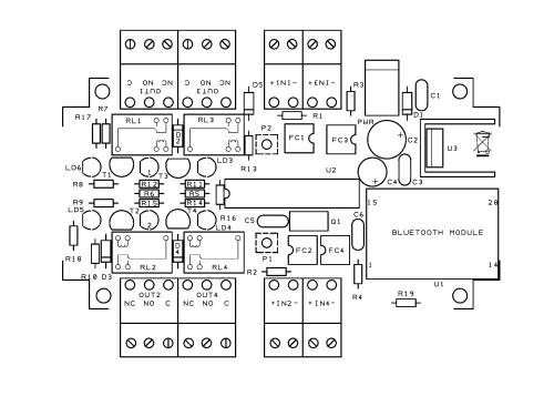
The Wiring Diagram

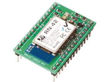
The circuit diagram of the board is developed around the U2 microcontroller (a PIC16F876A from Microchip) and, obviously, the Bluetooth RN -42 module (U1). The PIC controls the relay by means of four I/O lines configured as outputs, each of which drives a NPN transistor used as a power amplifier and static swich. The micro reads the four optocouplers through as many respective I/O lines and can be used to detect the status of the level of tension on inputs: when 5÷30 V are applied to the IN1 … IN4 terminals, the output of the optocoupler goes into saturation and closes the PIC’s RB1, RB6, RB0, RB7 inputs to ground, so that they receive the low logic level.
Finally, the circuit has a power supply section (U3, an LD1086-3.6 regulator that provides the 3,6 volt power supply) and 2 buttons (P1 and P2) plus two more LEDs (yellow and green) used for the selection/signaling of operating modes.
The circuit is powered by the plug dubbed PWM, to which, a power supply between 12 and 15 Vdc must be connected.
The Firmware
The firmware of the microcontroller has been designed to handle the serial communication protocol of the new module (via UART), however, all of the previous features have been retained. The full matching in the switching between modes was also kept.
The micro firmware handles the communication with the U1 module, and cyclically reads the logic state of the photo-couplers corresponding to the inputs and, depending on the mode and the commands received, puts at high or low level the outputs which are managed by the output relay. When starting the PIC initializes its lines by setting RA1, RA2, RA3 and RA5 as outputs for the control of the relay and RB0, RB1, RB6 and RB7 as inputs (internal pull-up) for reading the output levels of the opto-couplers; RA0 and RB3 are configured as outputs and used to turn on the indicator LED while RB4 and RB5 are configured as inputs (internal pull-up) for reading the buttons. Finally the internal firmware uses the UART to communicate with the Bluetooth module.
The first operation performed is to check which buttons are pressed: if both the storage structure of the MAC address is set to zero of the enabled slave Bluetooth unit, if only P1 is pressed the automatic mode of operation is activated. If the only button to be pressed is P2, it sets the manual mode (command). Otherwise no operation is performed and it retains the last stored mode.
Later, through the appropriate commands (see the previous posts on the Bluetooth component), it configures the RN-42 module: in particular it sets whether it should work as slave (“MS, 0” command) or as a master (“MS 1” command). Also it sets the default PIN code (“1234”).
Please note that if you select the automatic mode at startup, you can switch from ‘ automatic to semi-automatic and vice versa through the pressure of P1 during normal operations.
Instead, in these two modes, P2 is used to start the Bluetooth pairing procedure: the RN-42 module scans and stores the MAC of the first 5 Bluetooth devices identified.
Finally you enters the main operative section of: in the command mode operating through the data sent/received by RN-42 the hardware in/out and communication with the Android software are handled, in the other modes the PIC cyclically controls the module to perform Bluetooth scans and, depending on the responses received and the hardware inputs, it enables or disables corresponding outputs.
Download the Firmware
Android Software
The software developed for Android (“littleBlueControl”) allows the connection and the remote management of the board in case you choose the Command mode: You can check the current status of the digital inputs, check the output status (ON or OFF) and change its value according to your needs.
After the the software startup screen a scan is started and Bluetooth devices within the coverage area of the smartphone are detected.
The list shows both already paired and the newly detected systems; clicking on the board item (Vecchia Scheda I/O,in our example) you pick it and start the connection. There is also a button to request a new execution of the scan and update the list.
At this point, if it is the first time that the device is detected, you are asked to enter the PIN code (default is 1234). Then, you switch on the program’s main screen in which, starting from the top, you can see the status of the four relay outputs and of the same number of photocoupled inputs.
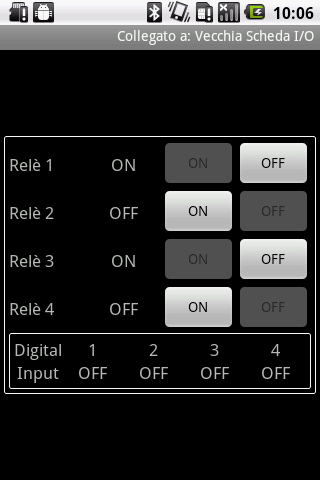
For each output the following notation is used: on the left is a text label indicates current status while on the right, 2 buttons (labeled with ON and OFF of which only 1 is enabled) can be used to change the status.
On the other hand, only one text label showing the current status is available on inputs: ON in the case that the input voltage applied is enough to activate the same, OFF otherwise.
Returning again to the outputs, to request a change in the current state simply click on the button: at that point the selected command is sent to the board and, on your smartphone, a window will will show up and shows you the command is sent. When the procedure is completed, the GUI is updated.
Lastly, note that Android software has a timer for the graphics to update. In fact, the software cyclically connects to the board, to read the current status and update the graphical user interface (in particular, if the status of inputs changed, the respective viewport is changed).
Download APP Android
The communication protocol
When command mode is selected, the communication protocol between the board and the smartphone provides that it will act as a Bluetooth master, while the board will behave like a slave.
The protocol assumes patterns consisting of 4 bytes structured as follows:
– first byte: type of operation (read or setting I/O); GETNFO_CMD (bytes 0x41) for reading; SETNFO_CMD (byte 0x42) for setup;
– second byte: Type of resource identifier. There are 3 possibilities: board’s complete state (STATUS_CMD; byte 0x40); single relay output (OUTRLE_CMD; bytes 0x41), and finally single digital input (INPDIG_CMD; bytes 0x44)
– third byte: ID of the resource;
– fourth byte: state of resource setting (only for setting relay outputs.)
The protocol also provides that the slave responds with confirmation packets to any command request from the master,
Modes of Operation
As a recap, this system presented and descripted in details in this post operates in three distinct modes:
– Manual (control): The unit performs the commands given from an Android device through Bluetooth communication protocol. It’s possible to enable or disable individual relay or read and display graphically the logical state of opto-isolated inputs.
– Automatic: if one or more of the 5 Bluetooth devices stored enters the area of coverage, the PIC activates the RL1 relay that remains energized until when all enabled devices do not come out from the area.
– Semiautomatic: the photocoupled inputs determine the condition of the relevant relays, but only when at least a Bluetooth enabled device enters the coverage of the corresponding relay is triggered (in particular, RL1 for IN1, RL2 for IN2, RL3 for IN3 and RL4 for IN4).
In the store

can you do it to 8 relay channel output control, instead 4 in and 4 out?
You have to modify the PCB, the Firmware anche the Android APP.
But you can do it without problem
Can I used it to count pulses per 10 minutes from an energy meter? These pulses are about 100ms long.
No, I’m sorry it’s not for this application. But you can modify the firmware.
Have you see this one?
http://www.open-electronics.org/how-to-create-an-intelligent-web-enabled-power-meter-with-arduino/
I have an app running in an android tablet. Can I interface with this device to read the status of the 4 inputs?
You have to use our app
Is there any chance to get he code in English? I have a project that I need to interface a PIC18 with a RN41 module
Will you please pass me the compiled app to install apk, or this takes some type of setting for the pic?
Interresting device.