Let’s learn about hardware and software features of the open source 3D printer from Open-Electronics.
Among the advantages of open source hardware and software lies the ability to know all the construction and design details and have access to all the parameters to change the device operation in details.
We have all the information and the sources by which to implement our mods in an easy manner. What’s required in return is some sort of commitment to share back our work with the community in order to keep the virtuous circle of development going free and shared.
As 3Drag belongs to the Rep Rap Open Source printers family it’s then made to benefit from the new developments from the community and, at the same time, be an inspiration for other Rep Rap devs.
The Firmware
Here we present the configuration for Sanguinololu board, but in the next posts we’ll present our board using an ATmega2560 and with much more efficient features.
The software for the Sanguinololu board on 3Drag is responsible for managing the basic functions of the printer and interprets the various G-Code commands and turn them into motor and extruder movements.
The code is obviously made compliant to the conventions of all RepRap projects, and it’s possible to use a configuration file to define mechanical and electronic characteristics of the printer.
Each firmware thus provides configs for the three motors (one for each axis), one motor for each extruder, the heater together with its thermistor control, the heated plate, the cooling fans and a microswitch for adjusting the start/end position.
Configuring 3Drag
Since we have chosen the Marlin Firmware reference variables will be those related to that: their name and description will help you to find the homologous variables in other firmware, in case you want to try them.
Let’s start by saying that every firmware must know the type of card being used: in our case is a Sanguinololu 1.2, usually identified with the code number 62 in the boards inventories:
// Sanguinololu 1.2 and above = 62
#define MOTHERBOARD 62
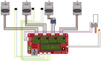
With this information, the firmware is compiled with the correct pin configuration, assigning the various digital and analog pins to the relative resources such the as steppers power modules or the start / stop switches.
Here you can see the wiring diagram of this card so that you can have a reference of the electrical connections on board, motors and microswitches.The next parameter is the type of NTC used.
3Drag uses a 100K NTC and we do not have the heated platen which should be combined with another NTC sensor. For these reasons, in the area allocated to the sensor settings you must have the type 5 for Temp_Sensor_0 and we must also ensure that there is no sensor associated with the plate (Bed_Sensor_0). In case you don’t check, the firmware would wait the plate to reach the proper temperature and printing would never start.
//============== Thermal Settings======================
//=====================================================
// 5 is 100K thermistor – ATC Semitec
// 104GT-2 (4.7k pullup)
#define TEMP_SENSOR_0 5
…
#define BED_SENSOR_0 0
The next section to take care of is the microswitches start zone, ie those three switches that allow the firmware to detect the boundaries of the X/Y area, together with the point from which to start to deposit on the plate of the printing material (Z axis).
We have chosen to use the solution “Normaly closed” in order to immediately stop the engine if the connection is interrupted or the switch is defective. This mode requires the Boolean value “false” for the four constants that tell the firmware if the logic is reversed (our it’s not, and the switch opens the circuit when actuated). In general, if a switch has an important role, as for example the engine retainer at the beginning or end of cycle, or a safety lock, it is good practice to use it in the NC mode (normally closed) so as to have a protection compared to its malfunction.
const bool X_ENDSTOPS_INVERTING = false;
// set to true to invert
// the logic of the endstops
const bool Y_ENDSTOPS_INVERTING = false;
const bool Z_ENDSTOPS_INVERTING = false;
Once the logic is defined, now we must passed on to the firmware the switch position: 0 position of each axis can be at the beginning or end. If it is at the beginning (value “-1” or MIN) the firmware will move the printing plate toward the axis start position (0) and will stop when the switch is actuated. If the switch is set with the maximum value of the axis (at the end) by the value “1”, the firmware would move the plate towards the end position to activate the switch and then revert back of the preset length for that specific axis. For practical reasons, the regulation of the coordinates X = 0, Y = 0 and for the screws tuning, the switches are positioned at the beginning of the stroke of the axis and then all the values of the three constants are set to “-1”
// ENDSTOP SETTINGS:
// Sets direction of endstops When homing
// 1 = MAX, -1 = MIN
# define X_HOME_DIR -1
# define Y_HOME_DIR-1
# define -1Z_HOME_DIR
As said above, in searching the “home ” position which corresponds to” 0 “, the firmware still keeps control of the measures for each of the axes, so as to avoid damage due to displacements beyond the physical limit of mechanics. Since we only use the switches for the movement start (and not a start / end couple for each axis), the firmware requires the minimum and maximum values beyond which, once done the reset, the motor stops.
In the case of 3Drag, the limit is equal to the volume of the plate with one centimeter tolerance on each side. Set the minimum and maximum values to those of the print area helps avoid the risks of a blocking due to displacement.
For the 3Drag, then, X and Y range from 0 to 200, while Z can be up to 220 mm .
// Travel limits after homing
# define X_MAX_POS 200
# define X_MIN_POS 0
# define Y_MAX_POS 200
# define Y_MIN_POS 0
# define Z_MAX_POS 220
# define Z_MIN_POS 0
Now it’s the turn of pulleys and belts. The mounting of these determines the movement of the printing plate and of the extruder. The parameter has been called “Invert_<asse>_ Dir” and can be true or false.
With the 3Drag the X, Y and Z axis are set to “false”, meaning they are not to be reversed as a movement, while the extruder is to be reversed as there is a small gear which drives the large gear wheel which is fixed to the bolt: this mechanism actually determines the reversal of the direction of rotation.
# define INVERT_X_DIR false
# define INVERT_Y_DIR false
# define INVERT_Z_DIR false
# define INVERT_E0_DIR true
# define INVERT_E1_DIR true
# define INVERT_E2_DIR true
The stepper motors, when powered, remain locked in their position and give a significant resistance to movement: this has the side effect of a significant current consumption and the consequent heating of the motor and electronics.
// Disables axis when it’s not being used
#define DISABLE_X false
#define DISABLE_Y false
#define DISABLE_Z true
#define DISABLE_E false // For all extruders
Final parameter to setup is the number of steps that each motor must take to perform a shift by one unit of measure (in our case 1 mm). Everything should be processed according to the settings of the board and drivers: you can manage the full step or 4, 8 or 16 microsteps. 3Drag’s engines are 16 microsteps managed, leading to a complete revolution of 3200 microsteps. To avoid complicate too much your life, you can use directly these settings: 64.25 for X and Y, 2560 for Z, and 654 for the extruder. For the latter, counts were made according to the actual length of the wire used to per respect to that provided by the software slicing, finding the value that is the closest to reality.
// default settings
# Define DEFAULT_AXIS_STEPS_PER_UNIT {64.25,64.25,2560 , 654}
This section is about speeds and accelerations: the values point out the maximum that can be applied by the firmware and let the mechanics operate as effectively and quickly, avoiding resonances or going beyond the physical limits.
First, let’s set the values for the maximum linear speed of the axes and the extrusion process. In the case of 3Drag the value can be increased to 500 mm / sec (a shift of half a meter per second) for both, the two axes of the plate, and the extruder.
The Z axis is instead limited to 50 mm / sec as it is very geared down (2560 steps to make 1 mm) and a greater speed would require the rotation of the motor beyond its normal operating specifications.
# Define DEFAULT_MAX_FEEDRATE {500, 500, 50, 500} // (mm / sec)
The speed is then operated with an acceleration value expressed in mm / sec*sec that brings the motor from standstill to the desired speed. Too high accelerations, however, may bring the structure to vibrate and bad manage movements that are small and alternating (eg: a fill of a narrow wall for example), then it is a value to be tuned according to the job you want to print.
// X, Y, Z, E maximum start speed for accelerated moves.
# define DEFAULT_MAX_ACCELERATION 9000,9000,100,10000 {}
// X, Y, Z and E max acceleration in mm / s ^ 2 for printing moves
# define DEFAULT_ACCELERATION 1000
// X, Y, Z and E max acceleration in mm / s ^ 2 for r retracts
# define DEFAULT_RETRACT_ACCELERATION 1000
The standard acceleration parameters for wire printing and retraction are defined in two specific lines and, from our tests, the value of 1000 is well suited to the structure.
Programming the Firmware
3Drag comes with an already programmed firmware.
Programming the board is made via the same USB connection used to drive the printer and this is a nice legacy of Arduino compatibility.
At the time of writing, you must use the 022 version of the IDE, available at arduino.cc/en/Main/Software in the “Previous IDE Versions”
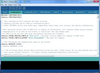
You can download the source file with the configuration from our website and, once opened,you will see a series of tabs on the IDE.
The second tab is called “Configuration.h” and contains various parameters that we have described.

To program the Sanguinololu board from the Arduino IDE you need to add the files related to the hardware. You can find them on the Sanguinololu site code.google.com/p/sanguino/downloads/list and the contents of the ZIP that you download should be moved in the “hardware” folder of the Arduino IDE.

Obviously, before you can program, you must also choose the COM port to be used (“Serial Port”) and ensure that there is nothing dialoguing with the printer (such as the printer software) and that the programming jumper is inserted on the Sanguinololu card (it’s in the middle of the microcontroller, on the driver side).
The plate
A good grip, even for prints of huge length and a reasonable ease in removing the objects are all characteristics related to the printing plane that for 3Drag that is made of fiberglass and is not heated (you can still add a heated floor without any problem by the way).
If you plan to use the PLA, you have to make the surface slightly porous and expose the fiber glass from the inside. It seems complicated but it’s not: just use a scouring pad to transform the surface from polished to opaque , it makes ideal for printing with PLA.
At the end of the test prints, raise the printed object with a wide blade knife, starting from one corner. If the object is thin it will be easier, and if it is thick or solid, you have to use more patience and detach it from more points.
Tackling the gap with the BRIM
The “brim” is the new ally to complete challenging prints and tame the heat recoil even on unheated plates.
The idea is to create a platform that follows the object’s perimeter, with a width defined by the user. Being a single layer, the thermal retraction is counterbalanced and hindered by the huge surface contact with the printing plate.
After printing, the edge helps to detach the object more easily as the blade slips under the piece guided by thin platform which, thanks to its flexibility, is easy to detach. With a cutter you must then remove the platform that, as you’ll see, is very well attached to the rest of the piece.
The dimensions of the Brim are to be set in the print profile and are in the same Slic3r tab dedicated to the skirt.
Add an adhesive layer
There are cases in which printing requires a very firm grip on the plate, as for example for vessels with a very small base and a certain weight, or subjects who have a pedestal and then grow in height as busts and statuettes.
For these, fiberglass adherence is not sufficient and you may try alternative solutions. The most common is based on vinyl glue: when diluted with water in equal parts it can be spread on the printing plate simply brushing as if you were wetting the entire surface. When the layer is uniform, it must be left to dry with a little of patience before printing: wait until it dryes up to the touch and it’s no more sticky.

When I print the GyroCube,the X axis skip.
(perimeter_speed = 90
infill_speed = 90
travel_speed = 140)
Unfortunately I burn the control board when adjust
the stepper driver.
I have to buy a new one.
And how many Vref of the A4988 do you recommend?
Hi, the Vref MUST be 0.4V. Higher value burn the chip. You can buy only the driver
http://store.open-electronics.org/3D/3D_electronics/stepper_driver
Thanks.
I’m sure that my control board is also dead.
I have ordered one controller(with driver).
Now I wired the RAMPS 1.4 to 3Drag,but I preferred
3Drag’s controller.
I hope that I can make the printer run as fast
as 150 mm/s.
I own a 3Drag and I am impressed by what it can do. Really a good product,
I have one question: the X and Y pulleys are T5 Z10 (10 teeth) and the primitive diameter shoould be 15.915 mm. Each revolution measure p * Z=50.00mm on the primitive diameter. So the actual steps for a travel of 1mm are 1/(50/3200)=64 and not 64.25 as you write.
Thank you
Regards
DC.
Seconded, this is where my errors in size came from. If your measures are still off, look at horizontal size compensation.