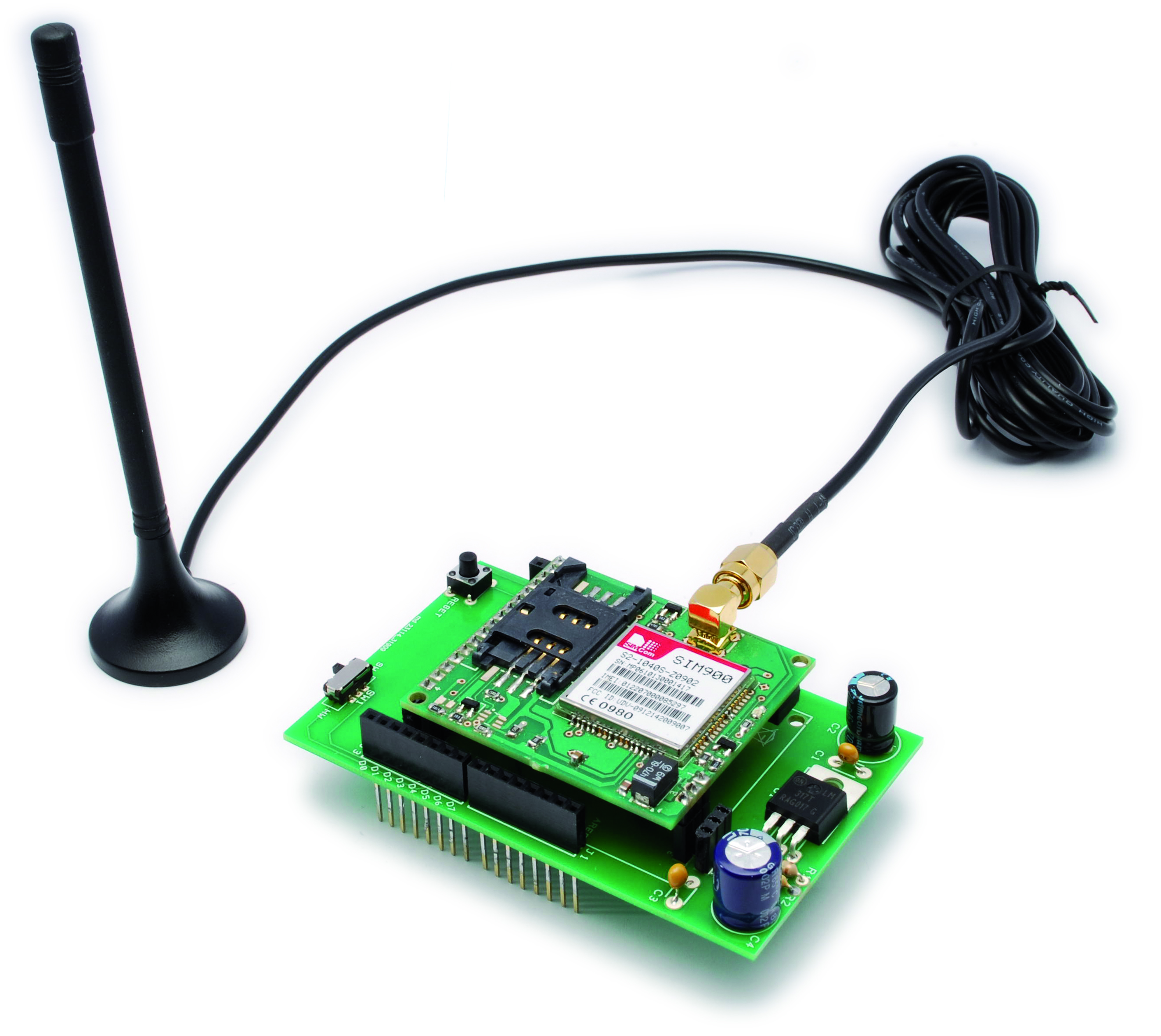

This is a very low cost and simple Arduino GSM and GPRS shield. We use the module SIMCom SIM900. It’s the cheaper module now avalaible in the market. The module is not simple to mount by an hobbyst, so we use the Breakboard TDGGSM_900 that we presented in this post.
You can buy the GSM module premounted from our cart.
To connect this module to Arduino we make a PCB that include a LM317 some capacitor filter and no more.
The LM317 give to module about 3.9V.
There is a switch to select the way to comunicate with arduino:
– throw serial hardware (pin 0 and 1)
– throw serial software (pin 4 and 5)
R1: 470 ohm
R2: 1 kohm
C1-C3: 100 nF
C2-C4: 470 µF 25 VLU1: LM317
GSM: TDGGSM_900 module
SW1: switch
P1: Microswitch
Selecting the serial hardware there are no problem with the baudrate (the default module baudrate is 115200) but there are problem programming the module (the serial is also used to upload the sketch).
Using instead the pin 4 and 5 there aren’t problems to upload the sketch but the maximum baudrate for NewSoftSerial (the serial library) is 57600.
We performed a GSM library to controll easly the module. The GSM library is a modified version of the library of HWKitchen.
With our version we controll the module throw the pin 4 and 5 (so normal digital pin) and our GSM libray include also the NewSoftSerial, so you can easy control the module, send and read SMS, make call, control the GSM state ecc.
Download GSM_Shield_Library
New GSM/GPRS library
This is the GSM_shield library documentation:
[newsletter_lock]
Here is a GSM_shield Library intended for GSM Shield by Futura Elettronica (www.futurashop.it).
This Library is derived from Hwkitchen’s GSM Library http://www.hwkitchen.com and include the NewSoftSerial library to comunicate using the pin 4 (RX) and 5 (TX).
You can also use the pin 0 and 1 (RX and TX) but you must disconnect the module to upload the sketch (so it’s not very nice), and you must modify the library.
How install the library for Arduino
After downloading of the GSM_Shield Library unzip the GSM_Shield folder to Arduino
Folder\libraries\ (es. C:\Programs\arduino-0022\libraries\GSM_Shield)
In the GSM_Shield.zip you can find the library to comunicate with gsm module and the file for use the NewSoftSerial.
Basic description
GSM_Shield library is created as standard class with the Gsm_Shield.cpp and Gsm_Shield.h source files. GSM_Shield class is based mainly on the serial communication
between the Arduino board and the GSM module placed on the GSM Shield. There are used standard AT commands for the communication with the GSM Module.
The Current version of library uses blocking version of communication.
It means that the program is blocked until the communication function is finished – so until required data are sent and required answer is received. The Advantage of that blocking approach is that it is easy to
understand the program flow. On the other hand there is also disadvantage that we can’t use the processor resources in the time when the program just waits for the incoming data.
Note: please pay attention to serial comunication mode. With the serial hardware (pin 0 and 1) you can reach the default baudrate of the module SIM900 (115200). But if you use the pin 4 and 5 the NewSoftSerial library can’t support (receive) the baudrate, so you must chose a lower baudrate.
With the command TurnOn(baudrate) you turn on the module and fix the baudrate. e.g. TurnOn(9600);
Methods
There are described important functions for the end user in this document.
The GSM_Shield Library contains also some functions that are used internally
and are not described in the document. It is also possible to use these
functions by the end user of course as they are defined as public but there
is needed to check the library source code with notes.
int LibVer(void)
returns library version in format XYY -it means X.YY (e.g. 100 means vers. 1.00)
Sample: GSM_Shield_LibVer
void TurnOn(baud)
turns on the GSM module in case module is off and sends some initialization AT commands which are possible to send before registration -> InitParam(PARAM_SET_0)
Should be used at the beginning of the sketch in the setup() function.
Set also the module baudrate (Note: if you use the hardware serial, there are no limit to the baudrate, 115200 is possibile. But using the pin 4 and 5 the NewSoftSerial must be use and the baud limit is 57600).
baud value possibile: 4800, 9600, 19200, 38400, 57600, 115200(no use with this library which include NewSoftSerial)
void setup()
{
gsm.TurnOn(9600);
}
Sample: GSM_Shield_LibVer
void InitParam(byte group)
Sends parameters for initialization of GSM module
group: 0 – parameters of group 0 – not necessary to be registered in the GSM
AT&F
1 – parameters of group 1 – it is necessary to be registered
AT+CLIP=1
AT+CMEE=0
AT+CMGF=1
Sample: GSM_Shield_LibVer
void Echo(byte state)
Function to enable or disable echo
Echo(1) enable GSM echo mode
Echo(0) disable GSM echo mode
Sample: GSM_Shield_LibVer
byte CheckRegistration(void)
checks if the GSM module is registered in the GSM net.
This method communicates directly with the GSM module in contrast to the method IsRegistered() which reads the flag from the module_status
(this flag is set inside this method)
must be called regularly at the one place in the main sketch loop
(recommendation repeat time is from 1sec. to 10 sec.)
return valus:
REG_NOT_REGISTERED – not registered
REG_REGISTERED – GSM module is registered
REG_NO_RESPONSE – GSM doesn’t response
REG_COMM_LINE_BUSY – comm line is not free
Sample: GSM_Shield_Reg
byte IsRegistered(void)
returns flag if the GSM module is registered in the GSM net
this method does not communicate directly with the GSM module,
just reads the flag so it is very fast unlike CheckRegistration()
which takes more than 20msec.
it is recommended to use this function everytime it is necessary to use some GSM function which needs GSM module is registered – checking ingoing SMSs, checking calls etc.
return valus:
0 – not registered
>0 – GSM module is registered
Sample: GSM_Shield_Reg
byte CallStatus(void)
checks call status
return values:
CALL_NONE – no call
CALL_INCOM_VOICE – incoming voice call
CALL_ACTIVE_VOICE – active voice call
CALL_NO_RESPONSE – no response
Sample: GSM_Shield_Call
byte CallStatusWithAuth(char *phone_number, byte first_authorized_pos, byte last_authorized_pos)
checks status of call(incoming or active) and makes authorization with specified SIM positions range
parameters and return values:
phone_number: a pointer where the tel. number string of current call will be placed so the space for the phone number string must be reserved
first_authorized_pos: initial SIM phonebook position where the authorization process starts
last_authorized_pos: last SIM phonebook position where the authorization process finishes
Note(important):
================
In case first_authorized_pos=0 and also last_authorized_pos=0 the received incoming phone number is NOT authorized at all, so every incoming is considered as authorized (CALL_INCOM_VOICE_NOT_AUTH is returned)
return:
CALL_NONE – no call activity
CALL_INCOM_VOICE_AUTH – incoming voice – authorized
CALL_INCOM_VOICE_NOT_AUTH – incoming voice – not authorized
CALL_ACTIVE_VOICE – active voice
CALL_INCOM_DATA_AUTH – incoming data call – authorized
CALL_INCOM_DATA_NOT_AUTH – incoming data call – not authorized
CALL_ACTIVE_DATA – active data call
CALL_NO_RESPONSE – no response to the AT command
CALL_COMM_LINE_BUSY – comm line is not free
void PickUp(void)
picks up the incoming call
Sample: GSM_Shield_Call
void HangUp(void)
hangs up call(incoming or active)
Sample: GSM_Shield_Call
void Call(char *number_string)
calls the specific number
e.g. gsm.Call(“+390123456789”);
void Call(int sim_position)
calls the number stored at the specified SIM position
e.g. gsm.Call(1); // call to the number stored at the 1st SIM position
char SendSMS(char *number_str, char *message_str)
sends SMS to the specific phone number
parameters and return values:
number_str: pointer to the phone number string
message_str: pointer to the SMS text string
return:
ERROR ret. val:
—————
-1 – comm. line to the GSM module is not free
-2 – GSM module didn’t answer in timeout
-3 – GSM module has answered “ERROR” string
OK ret val:
———–
0 – SMS was not sent
1 – SMS was sent 9/15
example of use:
gsm.SendSMS(“00XXXYYYYYYYYY”, “SMS text”);
char SendSMS(byte sim_phonebook_position, char *message_str)
sends SMS to the specified SIM phonebook position
parameters and return values:
sim_phonebook_position: SIM phonebook position <1..20>
message_str: pointer to the SMS text string
return:
ERROR ret. val:
—————
-1 – comm. line to the GSM module is not free
-2 – GSM module didn’t answer in timeout
-3 – specified position must be > 0
OK ret val:
———–
0 – SMS was not sent
1 – SMS was sent
an example of usage:
GSM gsm;
gsm.SendSMS(1, “SMS text”);
char IsSMSPresent(byte required_status)
finds out if there is present at least one SMS with specified status
if there is new SMS before IsSMSPresent() is executed this SMS has a status UNREAD and then after calling IsSMSPresent() method status of SMS is automatically changed to READ
parameters and return values:
required_status:
SMS_UNREAD – new SMS – not read yet
SMS_READ – already read SMS
SMS_ALL – all stored SMS
return:
ERROR ret. val:
—————
-1 – comm. line to the GSM module is not free
-2 – GSM module didn’t answer in timeout
OK ret val:
———–
0 – there is no SMS with specified status
1..20 – position where SMS is stored
example of use:
char position;
char phone_number[20]; // array for the phone number string
char *sms_text;
position = gsm.IsSMSPresent(SMS_UNREAD);
if (position) { // read new SMS
gsm.GetGSM(position, tel_number, &sms_text);
}
char GetSMS(byte position, char *phone_number, char *SMS_text, byte max_SMS_len)
reads SMS from specified memory(SIM) position
parameters and return values:
position: SMS position <1..20>
phone_number: a pointer where the phone number string of received SMS will be placed
so the space for the phone number string must be reserved – see example
SMS_text : a pointer where SMS text will be placed
max_SMS_len: maximum length of SMS text excluding also string terminating 0x00 character
return:
ERROR ret. val:
—————
-1 – comm. line to the GSM module is not free
-2 – GSM module didn’t answer in timeout
-3 – specified position must be > 0
OK ret val:
———–
GETSMS_NO_SMS – no SMS was found at the specified position
GETSMS_UNREAD_SMS – new SMS was found at the specified position
GETSMS_READ_SMS – already read SMS was found at the specified position
GETSMS_OTHER_SMS – other type of SMS was found an example of usage:
GSM gsm;
char position;
char phone_num[20]; // array for the phone number string
char sms_text[100]; // array for the SMS text string
position = gsm.IsSMSPresent(SMS_UNREAD);
if (position) {
// there is new SMS => read it
gsm.GetGSM(position, phone_num, sms_text, 100);
Serial.println(“DEBUG SMS phone number: “, 0);
Serial.println(phone_num, 0);
Serial.println(“\r\n SMS text: “, 0);
Serial.println(sms_text, 1);
}
char GetAuthorizedSMS( byte position, char *phone_number, char *SMS_text, byte max_SMS_len, byte first_authorized_pos, byte last_authorized_pos)
reads SMS from specified memory(SIM) position and makes authorization –
it means SMS phone number is compared with specified SIM phonebook position(s) and in case numbers match GETSMS_AUTH_SMS is returned, otherwise GETSMS_NOT_AUTH_SMS is returned
parameters and return values:
position: SMS position to be read <1..20>
phone_number: a pointer where the tel. number string of received SMS will be placed so the space for the phone number string must be reserved – see example
SMS_text : a pointer where SMS text will be placed
max_SMS_len: maximum length of SMS text excluding terminating 0x00 character
first_authorized_pos: initial SIM phonebook position where the authorization process starts
last_authorized_pos: last SIM phonebook position where the authorization proces finishes
Note(important):
================
In case first_authorized_pos=0 and also last_authorized_pos=0
the received SMS phone number is NOT authorized at all, so every
SMS is considered as authorized (GETSMS_AUTH_SMS is returned)
return:
ERROR ret. val:
—————
-1 – comm. line to the GSM module is not free
-2 – GSM module didn’t answer in timeout
-3 – position must be > 0
OK ret val:
———–
GETSMS_NO_SMS – no SMS was found at the specified position
GETSMS_NOT_AUTH_SMS – NOT authorized SMS found at the specified position
GETSMS_AUTH_SMS – authorized SMS found at the specified position
an example of usage:
GSM gsm;
char phone_num[20]; // array for the phone number string 12/15
char sms_text[100]; // array for the SMS text string
// authorize SMS with SIM phonebook positions 1..3
if (GETSMS_AUTH_SMS == gsm.GetAuthorizedSMS(1, phone_num, sms_text, 100, 1, 3)) {
// new authorized SMS was detected at the SMS position 1
Serial.println(“DEBUG SMS phone number: “, 0);
Serial.println(phone_num, 0);
Serial.println(“\r\n SMS text: “, 0);
Serial.println(sms_text, 1);
}
// don’t authorize SMS with SIM phonebook at all
if (GETSMS_AUTH_SMS == gsm.GetAuthorizedSMS(1, phone_num, sms_text, 100, 0, 0)) {
// new SMS was detected at the SMS position 1
// because authorization was not required
// SMS is considered authorized
Serial.println(“DEBUG SMS phone number: “, 0);
Serial.println(phone_num, 0);
Serial.println(“\r\n SMS text: “, 0);
Serial.println(sms_text, 1);
}
char DeleteSMS(byte position)
deletes SMS from specified SMS position
parameters and return values:
position: SMS position <1..20>
return:
ERROR ret. val:
—————
-1 – comm. line to the GSM module is not free
-2 – GSM module didn’t answer in timeout
-3 – position must be > 0
OK ret val:
———–
0 – SMS was not deleted
1 – SMS was deleted
char GetPhoneNumber(byte position, char *phone_number)
reads phone number string from specified SIM position
parameters and return values:
position: SMS position <1..20>
return:
ERROR ret. val:
—————
-1 – comm. line to the GSM module is not free
-2 – GSM module didn’t answer in timeout
-3 – position must be > 0
phone_number is empty string
OK ret val:
———–
0 – there is no phone number on the position
1 – phone number was found
phone_number is filled by the phone number string finished by 0x00
so it is necessary to define string with at least
15 bytes(including also 0x00 termination character)
an example of usage:
GSM gsm;
char phone_num[20]; // array for the phone number string
if (1 == gsm.GetPhoneNumber(1, phone_num)) {
// valid phone number on SIM pos. #1
// phone number string is copied to the phone_num array
Serial.println(“DEBUG phone number: “, 0);
Serial.println(phone_num, 1);
}
else {
// there is not valid phone number on the SIM pos.#1
Serial.println(“DEBUG there is no phone number”, 1);
}
char WritePhoneNumber(byte position, char *phone_number)
writes phone number string to the specified SIM position
parameters and return values:
position: SMS position <1..20>
phone_number: phone number string for the writing
return:
ERROR ret. val:
—————
-1 – comm. line to the GSM module is not free
-2 – GSM module didn’t answer in timeout
-3 – position must be > 0
OK ret val:
———–
0 – phone number was not written
1 – phone number was written 14/15
char DelPhoneNumber(byte position)
del phone number from the specified SIM position
parameters and return values:
position: SIM position <1..20>
return:
ERROR ret. val:
—————
-1 – comm. line to the GSM module is not free
-2 – GSM module didn’t answer in timeout
-3 – position must be > 0
OK ret val:
———–
0 – phone number was not deleted
1 – phone number was deleted
char ComparePhoneNumber(byte position, char *phone_number)
compares specified phone number string with phone number stored at the specified SIM position
parameters and return values:
position: SMS position <1..20>
phone_number: phone number string which should be compare
return:
ERROR ret. val:
—————
-1 – comm. line to the GSM module is not free
-2 – GSM module didn’t answer in timeout
-3 – position must be > 0
OK ret val:
———–
0 – phone numbers are different
1 – phone numbers are the same
an example of usage:
if (1 == gsm.ComparePhoneNumber(1, “123456789”)) {
// the phone num. “123456789” is stored on the SIM pos. #1
// phone number string is copied to the phone_num array
Serial.println(“DEBUG phone numbers are the same”, 1);
}
else {
Serial.println(“DEBUG phone numbers are different”, 1);
}
[/newsletter_lock]
Download GSM_Shield_Library
New GSM/GPRS library
In this page you can find some example.
Example to test library
/* GSM Shield example

 created 2011
 by Boris Landoni

 This example code is in the public domain.

 http://www.open-electronics.org
 http://www.futurashop.it
 */

#include <GSM_Shield.h>
//for enable disable debug rem or not the string       #define DEBUG_PRINT
// definition of instance of GSM class
GSM gsm;

void setup() {
  Serial.begin(9600);
  Serial.println("system startup");
  //gsm.InitSerLine(9600);   //initialize serial 1
  gsm.TurnOn(9600);              //module power on
  //gsm.InitSerLine(9600);   //initialize serial 1
  gsm.InitParam(PARAM_SET_1);//configure the module
  gsm.Echo(1);               //enable AT echo
}

void loop()
{

    int ver;
    ver=gsm.LibVer();
    Serial.print("Response Ver ");
    Serial.println(ver);
    delay(50000);
}
Example to network registration
/* GSM Shield example

 created 2011
 by Boris Landoni

 This example code is in the public domain.

 http://www.open-electronics.org
 http://www.futurashop.it
 */

#include <GSM_Shield.h>
//for enable disable debug rem or not the string       #define DEBUG_PRINT
// definition of instance of GSM class
GSM gsm;

void setup() {
  Serial.begin(9600);
  Serial.println("system startup");
  //gsm.InitSerLine(9600);   //initialize serial 1
  gsm.TurnOn(9600);              //module power on
  //gsm.InitSerLine(9600);   //initialize serial 1
  gsm.InitParam(PARAM_SET_1);//configure the module
  gsm.Echo(1);               //enable AT echo
}

void loop()
{

    int reg;
    reg=gsm.CheckRegistration();
    switch (reg){
      case REG_NOT_REGISTERED:
        Serial.println("not registered");
        break;
      case REG_REGISTERED:
        Serial.println("GSM module is registered");
        break;
      case REG_NO_RESPONSE:
        Serial.println("GSM doesn't response");
        break;
      case REG_COMM_LINE_BUSY:
        Serial.println("comm line is not free");
        break;
    }
    delay(2000);

    reg=gsm.IsRegistered();
      Serial.print("Registration ");
      Serial.println(reg);

    delay(50000);
}
Example to test call
/* GSM Shield example

 created 2011
 by Boris Landoni

 This example code is in the public domain.

 http://www.open-electronics.org
 http://www.futurashop.it
 */

#include <GSM_Shield.h>
//for enable disable debug rem or not the string       #define DEBUG_PRINT
// definition of instance of GSM class
GSM gsm;

void setup() {
  Serial.begin(9600);
  Serial.println("system startup");
  //gsm.InitSerLine(9600);   //initialize serial 1
  gsm.TurnOn(9600);              //module power on
  //gsm.InitSerLine(9600);   //initialize serial 1
  gsm.InitParam(PARAM_SET_1);//configure the module
  gsm.Echo(1);               //enable AT echo
}

void loop()
{

    int call;
    call=gsm.CallStatus();
    switch (call){
      case CALL_NONE:
        Serial.println("no call");
        break;
      case CALL_INCOM_VOICE:
        Serial.println("incoming voice call");
        delay(5000);
        gsm.PickUp();
        break;
      case CALL_ACTIVE_VOICE:
        Serial.println("active voice call");
        delay(5000);
        gsm.HangUp();
        break;
      case CALL_NO_RESPONSE:
        Serial.println("no response");
        break;
    }
    delay(1000);

}
Download GSM_Shield_Library
New GSM/GPRS library
Bigger example
/* GSM Shield example

 created 2011
 by Boris Landoni

 This example code is in the public domain.

 http://www.open-electronics.org
 http://www.futurashop.it
 */

#include <GSM_Shield.h>

//**************************************************************************
char number[]="+39123456789";  //Destination number
char text[]="hello world";  //SMS to send
byte type_sms=SMS_UNREAD;      //Type of SMS
byte del_sms=0;                //0: No deleting sms - 1: Deleting SMS
//**************************************************************************

GSM gsm;
char sms_rx[122]; //Received text SMS
//int inByte=0;    //Number of byte received on serial port
char number_incoming[20];
int call;
int error;

void setup()
{
  Serial.begin(9600);
  Serial.println("system startup");
  gsm.TurnOn(9600);          //module power on
  gsm.InitParam(PARAM_SET_1);//configure the module
  gsm.Echo(0);               //enable AT echo

}

void loop()
{
  char inSerial[5];
  int i=0;
  delay(2000);

    Check_Call(); //Check if there is an incoming call
    Check_SMS();  //Check if there is SMS
    //Check data serial com

    if (Serial.available() > 0)
    {
       while (Serial.available() > 0) {
         inSerial[i]=(Serial.read()); //read data
         i++;
       }
       inSerial[i]='\0';
      Check_Protocol(inSerial);
    }

}

void Check_Protocol(String inStr)
{
       Serial.print("Command: ");
       Serial.println(inStr);

  Serial.println("Check_Protocol");

    switch (inStr[0])
      {
       case 'a' :  //Answer
           if (gsm.CallStatus()==CALL_INCOM_VOICE){
             gsm.PickUp();
             Serial.println("Answer");
           }
           else
           {
             Serial.println("No incoming call");
           }
         break;

       case 'c': // C  //Call
         if (inStr.length()<2)  //To call variable 'number'    comand   c
         {
           Serial.print("Calling ");
           Serial.println(number);
           gsm.Call(number);
         }
         if (inStr.length()==2)  //To call number in phone book position   comand   cx where x is the SIM position
         {
             error=gsm.GetPhoneNumber(inStr[1],number);
             if (error!=0)
             {
               Serial.print("Calling ");
               Serial.println(number);
               gsm.Call(number);
             }
             else
             {
               Serial.print("No number in pos ");
               Serial.println(inStr[1]);
             }
         }
         break;

       case 'h': //H //HangUp if there is an incoming call
         if (gsm.CallStatus()!=CALL_NONE)
         {
           Serial.println("Hang");
           gsm.HangUp();
         }
         else
         {
           Serial.println("No incoming call");
         }
         break;

       case 's': //S //Send SMS
         Serial.print("Send SMS to ");
         Serial.println(number);
         error=gsm.SendSMS(number,text);
         if (error==0)  //Check status
         {
             Serial.println("SMS ERROR \n");
         }
         else
         {
             Serial.println("SMS OK \n");
         }
         break;

       case 'p':  //Read-Write Phone Book
         if (inStr.length()==3)
         {

           switch (inStr[1])
           {
             case 'd':  //Delete number in specified position  pd2
               error=gsm.DelPhoneNumber(inStr[2]);
               if (error!=0)
               {
                 Serial.print("Phone number position ");
                 Serial.print(inStr[2]);
                 Serial.println(" deleted");
               }
               break;

             case 'g':  //Read from Phone Book position      pg2
               error=gsm.GetPhoneNumber(inStr[2],number);
               if (error!=0)  //Find number in specified position
               {
                 Serial.print("Phone Book position ");
                 Serial.print(inStr[2]);
                 Serial.print(": ");
                 Serial.println(number);
               }
               else  //Not find number in specified position
               {
                 Serial.print("No Phone number in position ");
                 Serial.println(inStr[2]);
               }
               break;
             case 'w':  //Write from Phone Book Position    pw2
               error=gsm.WritePhoneNumber(inStr[2],number);
               if (error!=0)
               {
                 Serial.print("Number ");
                 Serial.print(number);
                 Serial.print(" writed in Phone Book position ");
                 Serial.println(inStr[2]);
               }
               else Serial.println("Writing error");
               break;

           }

         }
         break;

       }

    delay(1500);

    return;
 }

 void Check_Call()  //Check status call if this is available
 {
     call=gsm.CallStatus();
     switch (call)
     {
       case CALL_NONE:
         Serial.println("no call");
         break;
       case CALL_INCOM_VOICE:
         gsm.CallStatusWithAuth(number_incoming,0,0);
         Serial.print("incoming voice call from ");
         Serial.println(number_incoming);
         break;
       case CALL_ACTIVE_VOICE:
         Serial.println("active voice call");
         break;
       case CALL_NO_RESPONSE:
         Serial.println("no response");
         break;
     }
     return;
 }

 void Check_SMS()  //Check if there is an sms 'type_sms'
 {
     char pos_sms_rx;  //Received SMS position
     pos_sms_rx=gsm.IsSMSPresent(type_sms);
     if (pos_sms_rx!=0)
     {
       //Read text/number/position of sms
       gsm.GetSMS(pos_sms_rx,number_incoming,sms_rx,120);
       Serial.print("Received SMS from ");
       Serial.print(number_incoming);
       Serial.print("(sim position: ");
       Serial.print(word(pos_sms_rx));
       Serial.println(")");
       Serial.println(sms_rx);
       if (del_sms==1)  //If 'del_sms' is 1, i delete sms
       {
         error=gsm.DeleteSMS(pos_sms_rx);
         if (error==1)Serial.println("SMS deleted");
         else Serial.println("SMS not deleted");
       }
     }
     return;
 }
NEW GPRS FUNCTION
Test AT command
#include "SIM900.h"
#include <NewSoftSerial.h>
#include "inetGSM.h"

//GSM Shield for Arduino
//www.open-electronics.org
//this code is based on the example of Arduino Labs.

//Simple sketch to communicate with SIM900 through AT commands.

InetGSM inet;
char msg[150];
int numdata;
char inSerial[40];
int i=0;

void setup()
{
  //Serial connection.
  Serial.begin(9600);
  Serial.println("GSM Shield testing.");
  //Start configuration of shield with baudrate.
  //For http uses is raccomanded to use 4800 or slower.
  if (gsm.begin(4800))
    Serial.println("\nstatus=READY");
  else Serial.println("\nstatus=IDLE");
};

void loop()
{
  //Read for new byte on serial hardware,
  //and write them on NewSoftSerial.
  serialhwread();
  //Read for new byte on NewSoftSerial.
  serialswread();
};

void serialhwread(){
  i=0;
  if (Serial.available() > 0){
    while (Serial.available() > 0) {
      inSerial[i]=(Serial.read());
      delay(10);
      i++;
    }

    inSerial[i]='\0';
    if(!strcmp(inSerial,"/END")){
      Serial.println("_");
      inSerial[0]=0x1a;
      inSerial[1]='\0';
      gsm.SimpleWrite(inSerial);
    }
    //Send a saved AT command using serial port.
    if(!strcmp(inSerial,"TEST")){
      Serial.println("SIGNAL QUALITY");
      gsm.SimpleWrite("AT+CSQ");
    }
    //Read last message saved.
    if(!strcmp(inSerial,"MSG")){
      Serial.println(msg);
    }

    else{
      Serial.println(inSerial);
      gsm.SimpleWrite(inSerial);
    }

    inSerial[0]='\0';
  }
}

void serialswread(){
  gsm.SimpleRead();
}
GPRS Client
#include "SIM900.h"
#include <NewSoftSerial.h>
#include "inetGSM.h"

//GSM Shield for Arduino
//www.open-electronics.org
//this code is based on the example of Arduino Labs.

//Simple sketch to start a connection as client.

InetGSM inet;
char msg[100];
int numdata;
char inSerial[30];
int i=0;

void setup()
{
  //Serial connection.
  Serial.begin(9600);
  Serial.println("GSM Shield testing.");
  //Start configuration of shield with baudrate.
  //For http uses is raccomanded to use 4800 or slower.
  if (gsm.begin(4800))
    Serial.println("\nstatus=READY");
  else Serial.println("\nstatus=IDLE");

  //GPRS attach, put in order APN, username and password.
  //If no needed auth let them blank.
  if (gsm.attachGPRS("internet.wind", "", ""))
    Serial.println("status=ATTACHED");
  else Serial.println("status=ERROR");
  delay(5000);

  //TCP Client GET, send a GET request to the server and
  //save the reply.
  numdata=inet.httpGET("www.google.com", 80, "/", msg, 100);
  //Print the results.
  Serial.println("\nNumber of data received:");
  Serial.println(numdata);
  Serial.println("Data received:");
  Serial.println(msg);

  //Tweet
  //inet.tweet("*********************key************", "An Arduino at #cpes15");

};

void loop()
{
  //Read for new byte on serial hardware,
  //and write them on NewSoftSerial.
  serialhwread();
  //Read for new byte on NewSoftSerial.
  serialswread();
};

void serialhwread(){
  i=0;
  if (Serial.available() > 0){
    while (Serial.available() > 0) {
      inSerial[i]=(Serial.read());
      delay(10);
      i++;
    }

    inSerial[i]='\0';
    if(!strcmp(inSerial,"/END")){
      Serial.println("_");
      inSerial[0]=0x1a;
      inSerial[1]='\0';
      gsm.SimpleWrite(inSerial);
    }
    //Send a saved AT command using serial port.
    if(!strcmp(inSerial,"TEST")){
      Serial.println("SIGNAL QUALITY");
      gsm.SimpleWrite("AT+CSQ");
    }
    //Read last message saved.
    if(!strcmp(inSerial,"MSG")){
      Serial.println(msg);
    }

    else{
      Serial.println(inSerial);
      gsm.SimpleWrite(inSerial);
    }

    inSerial[0]='\0';
  }
}

void serialswread(){
  gsm.SimpleRead();
}
GPRS Server
#include "SIM900.h"
#include <NewSoftSerial.h>
#include "inetGSM.h"

//GSM Shield for Arduino
//www.open-electronics.org
//this code is based on the example of Arduino Labs.

//Simple sketch to start a connection as server.

InetGSM inet;
char msg[100];
int numdata;
char inSerial[30];
int i=0;
long lasttime;

void setup()
{
  //Serial connection.
  Serial.begin(9600);
  Serial.println("GSM Shield testing.");
  //Start configuration of shield with baudrate.
  //For http uses is raccomanded to use 4800 or slower.
  if (gsm.begin(4800))
    Serial.println("\nstatus=READY");
  else Serial.println("\nstatus=IDLE");

  //GPRS attach, put in order APN, username and password.
  //If no needed auth let them blank.
  if (gsm.attachGPRS("internet.wind", "", ""))
    Serial.println("status=ATTACHED");
  else Serial.println("status=ERROR");
  delay(5000);

  //Read IP address.
  int i=0;
  while(i<20){
    gsm.SimpleRead();
    i++;
  }
  delay(5000);
  gsm.write((const uint8_t*)"AT+CIFSR\r", 10);
  gsm.read(msg, 200);
  Serial.println(msg);
  delay(5000);

  //Tweet
  //inet.tweet("*********************key************", "An Arduino at #cpes15");

  //TCP Server. Start the socket connection
  //as server on the assigned port.
  Serial.println(msg);
  delay(5000);
  if (gsm.connectTCPServer(80))
    Serial.println("status=TCPSERVERWAIT");
  else Serial.println("ERROR in Server");
  lasttime=millis();
};

void loop(){
  //serialhwread();
  //serialswread();
  //Check if there is an active connection.
  if (gsm.connectedClient()){
    //Read and print the last message received.
    gsm.read(msg, 200);
    Serial.println(msg);
  }
};

/*
void loop()
{
  serialhwread();
  serialswread();
};
*/

void serialhwread(){
  i=0;
  if (Serial.available() > 0){
    while (Serial.available() > 0) {
      inSerial[i]=(Serial.read());
      delay(10);
      i++;
    }

    inSerial[i]='\0';
    if(!strcmp(inSerial,"/END")){
      Serial.println("_");
      inSerial[0]=0x1a;
      inSerial[1]='\0';
      gsm.SimpleWrite(inSerial);
    }
    //Send a saved AT command using serial port.
    if(!strcmp(inSerial,"TEST")){
      Serial.println("SIGNAL QUALITY");
      gsm.SimpleWrite("AT+CSQ");
    }
    //Read last message saved.
    if(!strcmp(inSerial,"MSG")){
      Serial.println(msg);
    }

    else{
      Serial.println(inSerial);
      gsm.SimpleWrite(inSerial);
    }

    inSerial[0]='\0';
  }
}

void serialswread(){
  gsm.SimpleRead();
}
Test SMS without GPRS function
#include "SIM900.h"
#include <NewSoftSerial.h>
//If not used, is better to exclude the HTTP library,
//for RAM saving.
//If your sketch reboots itself proprably you have finished,
//your memory available.
//#include "inetGSM.h"

//GSM Shield for Arduino
//www.open-electronics.org
//this code is based on the example of Arduino Labs.

//Simple sketch to send and receive SMS.

char msg[200];
int numdata;

void setup()
{
  //Serial connection.
  Serial.begin(9600);
  Serial.println("GSM Shield testing.");
  //Start configuration of shield with baudrate.
  //For http uses is raccomanded to use 4800 or slower.
  if (gsm.begin(4800))
    Serial.println("\nstatus=READY");
  else Serial.println("\nstatus=IDLE");

  //Enable this two lines if you want to send an SMS.
  //if (gsm.sendSMS("3471234567", "Arduino SMS"))
    //Serial.println("\nSMS sent OK");

};

void loop()
{
  char smsbuffer[160];
  char n[20];
  //Read if there are messages on SIM card and print them.
  if(gsm.readSMS(smsbuffer, 160, n, 20))
  {
    Serial.println(n);
    Serial.println(smsbuffer);
  }
  delay(1000);
};

[…] Arduino GSM shield – [Link] […]
“low cost”? A full cellphone with screen and keyboard costs 30$$!!
:-) Yes of course, but use a commercial cellphone is not very easy. All the device embedded like bluetooth, wifi are more expensive. The SIM900 “now” is the cheaper module.
[…] possible, it may not be practical to run out and collect data from the devices. That is where this GSM / GPRS shield comes in […]
[…] possible, it may not be practical to run out and collect data from the devices. That is where this GSM / GPRS shield comes in […]
Hi Boris
The fact that the module is cheaper than cell phones is not quite true. All of the “good old” Siemens/Benq phones have a serial AT interface which is very easy to use. Every time I need some GSM support, I grab one of them from ebay. You’ll find these models for around 10€ … Siemens C35 is my favorite.
Hi ben,
I think that this board is cheaper than other SHIELD, but could be that there are other solution… I hope… So I can use it ;-)
My shield it’s no a commercial device. Futura Elettronica sell the breakboard a 60 Euros. The prices is for one piece, with sim holder, with RF connector, with antenna and mounted.
I developed a lot of application with Siemen C35. Futura Elettronica sold these devices, but now not all cellular phone have a serial interface and C35 is not very easy to find.
Hi,
if you looking for something REAL low cost you need this:
Reuse your old personal phone with a 10$ interface board :)
Cheers
Yes franf but this with an external gsm. A siemens. Using this cellular phone Arduino needs only two cable. Tx and rx. No more. But that is another project. :-)
[…] another Arduino GSM shield – [Link] Tags: Arduino, GPRS, GSM, SIM900-based, wireless Filed in Arduino | 1 views No Comments […]
@FranF
I can’t get how to connect the “10$ solution” to Arduino.
Hello Boris,
I am working to realize this circuit but I have a GSM module problem.
In fact, during the startup of the circuit (arduino + GSM module), the GSM module LED does not stay illuminated. I measure with my voltmeter the voltage at pins 2 (GND) and 3 (vcc) and I just see that the voltage drop of 3.9 volts to 3.3 and decreased further to 3.1 and then turns off the modem itself.
My electric power input is a 5V 2A on my LM317.
I also use the program available on this page. But I have no debug displayed on the monitor’s serial port.
Do you have an idea for this problem?
Sincerely,
Charles
Just only the system startup message :)
Hi Charles,
the main power of arduino must be 12V. I think that the Arduino power circuit uses the 5V of USB if you use a 5V as input. Try 12V.
Please use the forum for technical problems :-)
http://www.open-electronics.org/forum/
Hello guys I can not register my sim on the network I get this
Message AT + CREG?
Help me
Check the main power. The GSM module has some spike when try to register. Also check the antenna. Be sure that antenna is not too near to GSM or SIM card.
how to control the peak? then I noticed that the LED flashes only when I load the software then just seems dead. please help me last night that there is fighting.
this is the log that I use the library GSM.h
system startup
AT
AT
AT
AT
AT
AT&F1
AT&F1
AT&F1
AT&F1
AT&F1
ATE0
ATE0
ATE0
ATE0
ATE0
AT+IPR=115200
AT+IPR=115200
AT+IPR=115200
AT+IPR=115200
AT+IPR=115200
AT#SELINT=1
AT#SELINT=1
AT#SELINT=1
AT#SELINT=1
AT#SELINT=1
AT#GPIO=8,1,1
AT#GPIO=8,1,1
AT#GPIO=8,1,1
AT#GPIO=8,1,1
AT#GPIO=8,1,1
AT#GPIO=9,0,0
AT#GPIO=9,0,0
AT#GPIO=9,0,0
AT#GPIO=9,0,0
AT#GPIO=9,0,0
AT#GPIO=5,0,2
AT#GPIO=5,0,2
AT#GPIO=5,0,2
AT#GPIO=5,0,2
AT#GPIO=5,0,2
AT#GPIO=8,0,1
AT#GPIO=8,0,1
AT#GPIO=8,0,1
AT#GPIO=8,0,1
AT#GPIO=8,0,1
AT#GPIO=10,0,1
AT#GPIO=11,0,1
AT+CREG?
GSM doesn’t response
Registration 0
There is no communication with the module.
Are you using the right pin? The library use the pin D4 and D5. And you must change the baud with the command TurnOn(9600)
Use a power supply 12V 1A.
Use the switch to use arduino hardware and food arduino usb to 5v.
i use the arduino for power the gsm shield and arduino power with usb.
The library uses the Newsoftserial, so you must use the other pin. And you must use the external power. 5V 500mA of USB are no enought.
and how the power? if the shield is on arduino?
plese help me. if you want my mail or skype ..
You must connect 12V to plug of Arduino. If you prefer you can use the forum in this site.
http://www.open-electronics.org/forum/
hello boris,
I bought the 12v power supply and works great! But I is very hot my arduino is normal? thanks to the availability
Hi,
yes it’s normal. The GSM shield hasn’t a high corrent consuming and the current is provided by LM317, but the Arduino 5V regulator must reduce the 12V to 5V for the microcontroller
Hi boris,
i have another problem i have an arduino 2009 and i need use an alalog interrupts
but i don’t resolve.
i need to monitor analog pin 0 when change state!
you have a solution?
thanks.
Unico, please use the forum for technical questions.
This can help you:
http://www.arduino.cc/cgi-bin/yabb2/YaBB.pl?num=1252021499
hello boris
I need a very simple program that sends a text message only to control an Arduino came with a switch!
can you help me??
I’m Italian!
You can check the text message and if the text contains a specific word Arduino active the output. I haven’t a sketch now, I do some test and I’ll pubblish it on Forum, But this the next week.
thanks.
I have for now a simple program to send an SMS?
for now you can tell me how to send a simple SMS with number and text from arduino to a mobile phone?
Check the page http://www.open-electronics.org/arduino-gsm-shield/4
here there is a test sketch. Using a serial interface and pressing the key “s” the Arduino send a SMS :-)
I’ve tried does not work me error!
I do not recognize gps shield “GSM doesn’t response”
why?
Could be because that is a GSM Shield ;-)
Check the forum and send your problem in the forum
I have a few question about this shield.
I’m a newbie to arduino and i’m not expert at all!
First question:
If i leave the switch on HW position can i use the serial monitor function?
Second question:
How can i activate the software emulation on pin 4 and 5?
I took a look also to the forum, but no answers i can understand. Could you be so nice to help me?
Thank you
Stefano from Udine
Hi Stefano, if you use the hd Serial there is a problem when you upload the sketch. The Serial monitor isn’t a problem: The sim900 accept only AT commands so reject the other datas.
The library implement the Serial software, so to use the pin 4 and 5 do nothing.
Doh!
Looks like something is not working in this case :(
Still receiving “no response” on the serial monitor interface, followed by “receiving sms from (position 65534).
I have checked all the connection and looks like they are all good.
The led on the top of this module only blink when i power on, is that ok?
Power is applied to the GND and VIn pins and it’s regulated on 12.1V with a stabilized power supply. Power consumption is still only 0,06A, very strange, no?
I have also tryied differents simcard, but the problem still exist.
Sorry if i bother you, but it’s very important for me to make this work soon as possible :(
Are you using hd Serial or software serial? I suggest you to select sfw with the switch and non modify the library. Use a power supply 12V 1A. Check the LM317 output (must be 3,9V). The power consumption is ok. The led must blink slower when the gsm is connected and faster when search the network.
I have made tests with both the 2 setups, hw and sw. No changes have been done to the libraries. Power output on the LM317 was about 3.9V… until i made a short circuit whit my tester. End of games for today, i’ve burned up everything :(
Gonna buy another one… sigh
BTW thank you very much for your support, i will tell you when i make progress!
Check only the sw with this library version. Try to change only LM317. I hope that gsm module is ok.
I have the same problems Stefano.
But for now I have not burned anything.
I tried to replace the capacitors with a value of 1000 uF, but nothing, does not see the SIM900 GSM network.
After 3, 4 cycles, by calling the telephone number of the SIM900, it is present on the GSM network, but monitor the serial port always says “Registration 0”
Hi, please use the forum for technical questions.
Hi Boris, finally i got tonight at 21.00 the new GSM module (shop was closed but owner is my friend!)
I did exactly the same procedure as the last time and everything worked at first attempt.
I think i got a bad sim900 module first time, it’s normal to me to be unlucky :-)
Great job, it’s a very nice library! Going to study tomorrow, thank you very much!
Hi Boris, is there any library for this Shield including GPRS functions?
But maybe you can help me. I have to send to the modem a command to connect it to a website. Simply an url, is there a command to do that.
Thanks
Hi Nicola,
Marco Martines developed a new library with GPRS function here:
http://code.google.com/p/gsm-shield-arduino/
Hi Boris, if you mean the GSM Shield Library V2, I already downloaded it, but there aren’t GPRS funcution inside.
Regards
I think i found it in the update section.
Thanks and Regards.
Hi Boris, what’s the minimum voltage for the gsm shield? Can it run at 9V?
Thanks.
Yes, you can use 9V, but not with a battery. You must provide at least 1 A.
Hi, the AT+CSTT command to set APN always return TIMEOUT ERR value. Any advice to fix this problem?
Thanks
Have you downloaded the last version of the library? It includes GPRS functions
http://code.google.com/p/gsm-shield-arduino/
Hi Boris,
I just wanted to thank you for your help, and to let you know that the GSMShield works OK in USA with pre-paid AT&T SIM card.
Also, just in case somebody wants to use the board in USA: the SIM900 chip is certified in the USA and it has PTCRB, FCC and AT&T approvals.
Thank you,
Vadim
Hello! Where can I download the schematic of this shield? Is it opensourse?
Yes of course.
http://www.open-electronics.org/arduino-gsm-shield
Hi Boris!
I have assembld some gsm boards and seems network light keeps blinking after one second not 3 seconds, what might be wrong.
One board started working after desolderingg everythin and then soldering again.
One more question: Will this modem work with GPRS connectivity also.
Regards,
Ashwani Sihag
Hi Ashwani,
Did you buy this shield from open-electronics.org?
I don’t understand the problem.
The SIM900 support GPRS connections.
Hi Boris!
No but I have made these boards my self from your design. Making a GSM GPS tracker. One out of four gsm shield is working fine.May be some solder is dry but i m not sure. May be you seen the same kind of probolems when building your project.
I am sending location info by gprs and this needs a 2 amps peak sometime accourding to specs, so that is why i was asking you if your power supply is good enough to handle this.
I have not tried this but I hope you have tested GPRS.
Regards,
Ashwani Sihag
If a shield works I think that the problem is the solder or the components.
The LM317 provides enough current, plese verify the capacitors, they contrast the peaks.
Hi Boris!
All shields started working fine at their own, there was network registration problem day before yesterday and today everything working!
Thanks anyway!
I have a idea about of making a heartbeat sensor with gprs connectivity using atmega328 smd version for my dad so that he can wear the sensor like watch. What do you think, will that be useful for other people also? Just sharing because you seems a very creative person.
Regards,
Ashwani Sihag
I think that it’s a very important application.
How do you detect the heartbeat?
I think that a simple way is use a heartbeat sensor Polar RMCM01. But the person have to wear the Polar belt.
I’ll add a microsd to store the data and when something isn’t ok the sistem send a SMS.
With GPRS you can recover the SD data.
What do you think?
If I can help you… I’m here :-D
Hi Boris,
Thanks for inspiring me and for your help:-)
I have Polar sensor but I am trying to make a oximeter with some microcontroller with led light sensor on the finger. That will be more sleek design. SD card storing and then sending once is good idea.
But for time being I have a issue in this GSM shield: Today I assembled everything and tried sending data with GPRS , the arduino duemilanove hanged after AT+CSQ command. If i comment CSQ command then it works for few seconds and hang after sending data for once only.
GSM is working fine but atmega328 hangs, no response.
Do i need big capecator then 470uf on power supply board?
Regards,
Ashwani Sihag
Hello Boris,
I got the solution, was my mistake, I was using pin 8 and 9 as software serial for GPS and these pins are already wired for switcing on/resetting GSM modem.
May be Atmega328 was confused when I was reading the pins as GPS input while they were defined as output pin.
I have GPS tracker ready now. :-)
Regards,
Ashwani Sihag
Ok, I’m studing a new breakout with GPS and GSM. I’ll present it ASAP.
Hi Boris,
Exited to see your design.
I am also trying a new schematics with sim900 and sim18, both seems cheap solution with atmega328, all on same board.
Regards,
Ashwani Sihag
Hi Boris,
The caps(big blue, small black) on power board are diffrent then 470uf from parts list.
What are the values of caps in picture?
Regards,
Ashwani Sihag
Hello.
I am interested in an application with this GSM module,Seeeduino 212, and 6relay/6in shield. Is it possible to connect these modules?. Is there any incompatibility?
I also want to use a RTC,a keyboard 4×4 and a display 4×20 through I2C.
Greetings to all.
Hi Boris,
My name is Laura, and I am doing my final subject in the university to finish Telecomunications Engineer. I am working with HiloV2, Sagem technology. I have their evaluation board with the module.
I want to transmit information through my gateway to a CPU by SMS or email.
My problem is that Sagem do not give me a software to work, and I dont know how to start. I have already work with AT comands with Hyperterminal, but I think, that I need a program (script) to implement it authomatically isnt it?
thank you very much,
Laura
@ Ashwani
Both the capacitors are 470 µF, C2 is a 16VL and C4 is a 25VL, but you can use 25VL for both.
@ Ignacio
You can use the GSM shield with the Relay shield, but some pin are use from both the shield, so you must disconnect the RTS, CTS, DCD and DTR to recover some pins. The I/O connected to TX, RX, RST, RI and ON/OFF must be used only for the GSM shield, so you must renounce to some Input and Output on Relay shield.
@ Laura
Is the Sagem module a wireless CPU? Some GSM modules (like Wavecom) have inside a microcontroller that you can program with specific language (for Wavecom -> Open AT). If the Sagem hasn’t the CPU inside you must use a external microcontroller. Also SIM900 hasn’t the microcontroller inside, this is the reason why we developed the GSM shield. Through Arduino is possible control the module.
Hi Boris,
I am using an external microcontroller. I am programing with AT commands, but know I start using Linux (pppd), and when I try to connect with Internet to a web page (because the conection is stablish) I can`t. The modem give me the Ip and the DNS correctly.
It’s not very simple for me understand the problem. ASAP I’ll publish a solution with the GSM shield to make a internet connection and retrieve a page, but I’ll use a Arduino library.
Hi Boris,
I have seen logic level transition for rx tx in some other sheilds, why not this sheild?
Regards,
Ashwani Sihag
The current supplied by Arduino is not such as to damage the module, so there are no problems. In any case I suggest to provide a level translator in applications where the microcontroller has a higher voltage to the module. For example, in the TiDiGino project has not been provided any level translator since both the micro and the module are powered at the same voltage.
Hello, Boris:
I have the same problem as Stefano and Dodo. The module enters the network, but does not respond to serial communication. I made the same checks.
Hardware used:
Power source, Battery 12V, 7Ah., Seeeduino Mega.
Can you try with Seeeduino 328?
Could be that the problem is the different configuration of Mega pin.
Have you selected SW with the switch?
The micro is the ATmega 1280 @ 16MHz.
Yes, I checked in both switch positions. Indeed, it could be a matter of pins.
The problem is that the NSS http://arduiniana.org/libraries/newsoftserial/ doesn’t support the Arduino Mega. But you can use the Serial1 (pin 18 and 19) to comunicate with GSM. You must change the library (see also the TiDiGino library)
http://www.open-electronics.org/tidigino-contest/
Hello Boris,
The problem is in the library Newsoftwareserial. It is not compatible with arduino mega, any suggestions?.I need the mega for the I/O.
Thanks, in advance.
Sorry, had not updated the page and had not seen your answer.
Thank you.
Hi Boris,
i would like to use one sd shield but i need the pins 8, 10, 11 ,12 and 13.
How can i save the pins? (In reference to your reply to ignatio)
I tried to disconnect fisically the pins but i think i must modify the gsm library, right?
can you explain how?
maybe i can replace the pin 8 with another free pin in thearduino uno (changing the sd library).
But i need the pins from 10 to 13.
Thanks a lot!
demo
Hi, for gsm shield you have to connect 4, 5, 8 and 9 ports.
The other pin are not used, you can cut the track without problem.
No library modification is needed.
Hi Boris,
Do you know what is the diffrence between LM2596 ( with 5 legs)
power and our LM317 power supply…?I know that LM2596 will be expensive then LM317 , any other difference.
Regards,
Ashwani Sihag
The LM2596 provide more current but needs also more external components, because it’s a switching power supply. LM317 is a linear power supply.
Hi Boris,
I have not used SMF05C and R11 is 22ohm instead of 15 Ohm, how much this will effect the module? I have only one module working ok out of five, other four works sometimes and sometimes not.
What might be reason of restarting module rendomly?
Regards,
Ashwani Sihag
Hi Boris,
I found an incompatibility between the DS1307 (I2C interface)and the GSM Shield: each time I access the clock for having time data the program hangs up and often Arduino seems resetted: it begins the loop but it does not finish and stops or the setup is restarted: any suggestions? Incompatibility between wire.h or various RTC libraries and the GSM library?
Thanks
Sebastian
Hi Sebastian,
I think that the problem is due to some variable that go in overflow. GSM shield doesn’t use the A4 e A5 pins (the pins for i2cbus).
Hi Boris,
I think now I get it: I have on arduino a SD shiled for datalogging (note that I cut off the pins of the GSM Shield that are not used, i.e.: D13, D12, D11, D10 for avoiding interferences with the SD breakout board), a maxbotix ultrasonic sensor, a DS1307 clock and the GSM Shiled. This are the results:
SD + GSM Shield + Maxbotix = OK,
DS1307 + GSM Shield + Maxbotix = OK
DS1307 + SD + Maxbotix = OK
DS1307 + GSM Shield + SD + Maxbotix = System Stucks resetting itself (or so it seems) or blocks when opening the file on the SD for writing as soon a request is sended to the clock.
????????
Thanks anyway
Sebastian
I am quite sure that the problem is due to the sketch, not for electrical connection.
But it is difficult to understand the problem
Yes, I think the same thing: now I discovered that loading the wire.h library is enough to stuck everything…
Thanks
Sebastian
Ah ok,
when finish the projects if you like I’ll present it on this site.
HI..
i have a GSM Module (EZ10) i hope you help me
in connecting APR 9600 circuit with that module..
thanks….
Hello boris
I’m Italian and I do not know English
I have problems with the shield.
-trying to register the sim, with the example GSM_Shield_Reg, the answer is “modem not responding”
GSM_Shield_Call-example answers “no response”
-if I try to call the sim of the shield, the answering machine
power of the shield is with
power supply
Output of LM317 is 3.9V
why not go?
excuse for English
federico
:3 sorry also for the bad link
is the power supply
Hi, I don’t know this module, but if it use the AT command I think that with little work you can adapt this library and the GSM shield
Hi Federico.
Check the switch, the library use the NewSofSerial library, so the switch has to be on SFW indication.
The power is ok, 12V 1A is good.
Remove the SIM PIN code.
Use the antenna with cable, not a small antenna.
And keep me updated :-)
Thanks Boris.
Yes,
I set the switch on SFW, the antenna is with cable and the SIM does not have PIN code but the shield not work.
why?
federico
Contact our technical support to check your shield.
Hello boris,
I have several problems with the library, and I have stopped. Communication with the module is hardware (115000 bauds). Enter either network, send and receive sms and calls.
One problem is when I try to put the pin code (with AT commands, AT+CPIN=xxxx) “OK” is expected but the answer is not it(although if you get well then enters the network).
Another problem is that I read calls and sms with authorization but always responds that the phone is authorized but it is not.
Sample:
(error=gsm.GetAuthorizedSMS(pos_sms_rx,number_incoming,sms_rx,122,0,10);).
A warm greeting.
Hi,
If you use the hardware pins be sure to had modified alla library with the right serial comunication. Are you using an Arduino UNO or Mega?
The AT command for insert the PIN is right.
I tested all the HW kitchen library with the NewSoftSerial library and I don’t find any problem.
Send me the library so I can test it.
Hi Boris,
you were right! Attacching to an Arduino Uno the GSM Shield, the RTC Clock, the SD board and the Maxbotix sensor produces a RAM overflow even if I optimize the variables.
I solved the problem distributing the work on two Arduinos: one with the GSM shield and the other with datalogging functions.
Next step will be to try an Arduino Mega.
Now I get a new issue: as the GSM Shield drains out my battery very quickly I’m wondering if there is a way for turning off the module or to put it asleep.
Thanks
Sebastian
Hi,
Using MEGA, so I can not use the new software serial library.
I send you the libray modified. I only change “myserial” by “serial”,in everywhere.
@ Sebastian
yes, you can use the function AT+CFUN to go in low power mode.
But thi AT command isn’t implemented in the library.
You have to send it manualy,
@ Ignacio
try to use Serial1.
The Serial is also used to upload the sketch and for the debug.
See the TiDiGino library that is based on a atMega2560 and use the second serial.
Hello Boris,
Commenting on the new GPRS library.
You can use the new library by hardware?
You can use the new library with this GSM shield
what I meant, if possible use with hardware serial.
The library is for SIM900 GSM module.
I have connected the module to arduino mega.
I have downloaded the NEW GPRS FUNCTION and trying to send sms
When i upload the sketch the green led on the module blink and then turns off .
In the monitor i get :
GSM Shield testing.
status=READY
TEST
SMS sent OK
but no sms is recieved .
I using external battery 11V to power the arduino .
Any idea what is my problem ?
I have connected an FTDI to the computer and tested D5 and D4
on D5 i get :
AT
AT
AT
AT
AT
AT
AT
AT
AT
AT
AT&F
AT&F
AT&F
AT&F
AT&F
ATE0
ATE0
ATE0
ATE0
ATE0
AT+IPR=9600
AT+IPR=9600
AT+IPR=9600
AT+IPR=9600
AT+IPR=9600
AT+CLIP=1
AT+CLIP=1
AT+CLIP=1
AT+CLIP=1
AT+CLIP=1
AT+CMEE=0
AT+CMEE=0
AT+CMEE=0
AT+CMEE=0
AT+CMEE=0
AT+CMGF=1
AT+CMGF=1
AT+CMGF=1
AT+CMGF=1
AT+CMGF=1
AT+CNMI=2,0
AT+CNMI=2,0
AT+CPMS=”SM”,”SM”,”SM”
AT+CPMS=”SM”,”SM”,”SM”
AT+CPMS=”SM”,”SM”,”SM”
AT+CPMS=”SM”,”SM”,”SM”
AT+CPMS=”SM”,”SM”,”SM”
AT+CPMS=”SM”,”SM”,”SM”
AT+CPMS=”SM”,”SM”,”SM”
AT+CPMS=”SM”,”SM”,”SM”
AT+CPMS=”SM”,”SM”,”SM”
AT+CPMS=”SM”,”SM”,”SM”
AT+CPBS=”SM”
AT+CPBS=”SM”
AT+CPBS=”SM”
AT+CPBS=”SM”
AT+CPBS=”SM”
ATE0
AT+CMGL=”REC UNREAD”,1
AT+CMGL=”REC UNREAD”,1
AT+CMGL=”REC UNREAD”,1
AT+CMGL=”REC UNREAD”,1
on D4 i get lines of junk
Hi, the library uses the newsoftserial library that isn’t compatible with MEGA. You can modify che circuit to use the second serial hardware and modify the library to use this connection.
i am monitoring D4 and D5 with external FTDI and i see that the mega send valid commands
but the sim900 is responding with junk.
I have tryed to connect D5,D4 to arduino mega 50 and 51
and added :
#define _GSM_TXPIN_ 50
#define _GSM_RXPIN_ 51
in the GSM_GPRSLibrary_SMS
and still no response .
i have tryed this code :
void setup()
{
pinMode(8, OUTPUT);
digitalWrite(8, HIGH);
delay(1000);
digitalWrite(8, LOW);
delay(3200);
Serial.begin(9600);
Serial.print(“\r”);
delay(1000); //Wait for a second while the modem sends an “OK”
Serial.print(“AT+CMGF=1\r”); //Because we want to send the SMS in text mode
delay(1000);
Serial.print(“AT+CMGS=\”0544890044\”\r”); //Start accepting the text for the message
//to be sent to the number specified.
//Replace this number with the target mobile number.
delay(1000);
Serial.print(“SIM900 and Arduino say Hi!\r”); //The text for the message
delay(1000);
Serial.write(26); //Equivalent to sending Ctrl+Z
}
void loop()
{
//We just want to send the SMS only once, so there is nothing in this loop.
//If we put the code for SMS here, it will be sent again and again and cost us a lot.
}
i uploaded the scetch with SW1 to the reset switch and then moved the SW1 to connect to TX0 and RX0 and still no response from the module .
I veifyed that pin 3 on small conector has 3.7V
i dont know what else can i do to make it work.
Try the new version (3.06) on http://code.google.com/p/gsm-shield-arduino/
De-comment the line in GSM.h #define DEBUG_ON,
Change the pins in GSM.cpp
e run the sketch, then if it doesn’t work post the result log.
Hi,
I just bought this shield. However on the store page(http://store.open-electronics.org/Arduino_GSM_GPRS_shield), the first image shows that there are female header strips on it for expansion but shield on the succeeding images don’t have header strips.
Please confirm which is the one available in your store.
The shield use the long pin like the Strip6 and Strip8 that you can find in our store:
http://store.open-electronics.org/Arduino/Products/6pin_Arduino_Stackable_Headers
http://store.open-electronics.org/Arduino/Products/8pin_Arduino_Stackable_Headers
Hi,
I am new to arduino uno. I need to send sms the latitude and longitude coordinates obtained using gps module every 1 minute to a cellphone through gsm shield.Can you suggest some ideas for writting the code to implement the above mentioned task.
Hi Karthik,
I suggest you a GPS shield with the tinyGPS library http://arduiniana.org/libraries/tinygps/
With this library you retrieve the data and then is very simple send SMS with the GSM shield
Use the code
Serial.print(“Send SMS to “);
Serial.println(number);
gsm.SendSMS(number,text);
Hi Boris,
I connected DTR and RING INDICATOR pins of put Sim900 with Atmega328p for sleep mode.
After this connection sim900 rx tx stopped working. It happened with me on every board when I connect DTR and RING INDICATOR.
Regards,
Ashwani Sihag
Hi, the DTR is a input and RING is an output of the module. Configure the Arduino pin as input and output. And also use the command AT+CSCLK to configure the sleep mode.
Hi,
I configured one pin on atmega328 as interrupt handler listing to RI pin and another digital pin as DTR output.
Now atmega328 is not communicating, think damaged board.
I have tried this on 5 boards and all five are dead now on rx tx.
Regards,
Ashwani Sihag
GSM shield from arduino uno r3 to arduino mega 2056. I just use GSM_GPRSLibrary_AT to play with my new gms shiled sim900 and tested it on my arduino uno.
In the future i want to use it with ethernet shield so reading the .h file i undestand the shield use pin 4-5 (selector set to sw) and pin 8 and 9 (gmson and gsm reset) so i connect the pins to the erhernet uno using cable and everyting is fine, (4,5,8,9 plus power and ground).
When i do the same on the mega nothing appens, and with debug on these is the result
GSM Shield testing.
DB:NO RESP
DB:NO RESP
DB:NO RESP
ERROR: SIM900 doesn’t answer. Check power and serial pins in GSM.cpp
status=IDLE
Instead with Arduino uno
GSM Shield testing.
DB:ELSE
DB:ELSE
DB:ELSE
DB:CORRECT BR
can u help me?
thanks
Luigi
status=READY
OK
for my post i use the wrong library GSM Shield GPRS Library V3.07b (IDE 1.0) beta but now i have downloaded and used the right library and the response is always
GSM Shield testing (mega)
DB:DIFF RESP
DB:DIFF RESP
DB:DIFF RESP
ERROR: SIM900 doesn’t answer. Check power and serial pins in GSM.h
GSM Shield testing. (uno)
DB:CORRECT BR
status=READY
OK
so nothing as changed…. :-(
Hi Luigi,
the softserial is not supported from Mega on pin 4 e 6.
From the page http://arduino.cc/hu/Reference/SoftwareSerial
Not all pins on the Mega and Mega 2560 support change interrupts, so only the following can be used for RX: 10, 11, 12, 13, 50, 51, 52, 53, 62, 63, 64, 65, 66, 67, 68, 69
So you can change the pin.
Hi Boris, do you mean that on a Mega board I could change in the GSM.cpp file this line #define _GSM_RXPIN_ 5 to, for example, #define _GSM_RXPIN_ 52 and connect the D5 of the GSM shield (I got the old one) to the D52 of my Mega board?
Thanks
Sebastian
Hi,
I have the following question, can I connect a LCD display to show for instance the received sms on GSM shield?
Thanks
Valter
Yes of course,
Not all pin are used, you can use the free pin to drive the display.
Could you please summarize me the pin used by the GSM shield since I need to insert a LCD display and some button.
Thanks
Valter
In this post there is the schematics.
From the schema just 3 pin are left by the gsm module, if I can re-use some of module I cannot use it
You could disconnect the RTS, CTS, DCD and DTR to recover some pins. The pin TX, RX, RST, RI and ON/OFF must be used only for the GSM shield
Thanks Boris,
I discover the Arduino Mega with about 50 digital pins, this solve all my problems. Do you know if this GSM shield is compatible or I have to make some “manual” connection?
Valter
hello Sir…
i want try to make a home security system..and i plan to use sony ericsson cell phone (T610i/T28), arduino and PIR(passive infra red).
My question :
1. how about the source code??
same as the code above or the code is different not like above???
2. if the code is different, will you give me an example code??
I hope your help Sir..
i’m sory with my bad english… :)
Thanks.. :)
Hi Boris,
Thanks for the great library!
I am wondering if you are planning to implement the gsm.SetGPIOVal(GPIO10, 1); from the HW kitchen library?
I am having some trouble getting the arduino to act on the text it receives….
I am trying to use GETSMS_AUTH_SMS and then check the sms text for which pins to turn on or off.
Best regards,
Peter
Hi Peter
the HW library use a other module, not SIM900, and not all command are compatible.
Hi Boris,
I have noticed that many SIM cards stopped receiving sms using on the sheild after a while but able to send sms. Whats wrong?
That sim card works fine in mobile phone for sending a receiving sms.
Regards,
Ashwani Sihag
Hi, are you using the small antenna http://store.open-electronics.org/Accessories/Antennas/GSM%20antenna%20SMA%20connector
?
The problem could be the GSM field, you could protect the SIM card with aluminium connected to ground or put far the antenna.
Check also the power supply.
hi can anyone help me i want a project like if i send sms to arduino arduino turn on aircon any help plz!!!!!
The GSM/GPRS library could help you.
See also the TiDiGino project http://www.open-electronics.org/tag/tidigino/
Thank You Boris :-)..Yes I was using this antenna shown by you.
@Ashwani ;-)
Hi,
I’m trying to create a project with 2 Arduino GSM shield. A GSM module should communicate with each other with GPRS by exchanging data, but without going through the Internet and without using an internet provider. Where can I find an example to take some inspiration?
Thanks for your help.
Marco
Hei,
I just bought a GSM/GPRS shield and Arduino Uno R3.
I did download GSM Shield GPRS Library V3.08 (IDE 1.0) beta and uploaded “GSM_GPRSLibrary_Client” example script to arduino.
In GSM.cpp
#define _GSM_TXPIN_ 12
#define _GSM_RXPIN_ 13
And if i try to run the code I’m getting:
GSM Shield testing.
DB:NO RESP
DB:NO RESP
DB:NO RESP
ERROR: SIM900 doesn’t answer. Check power and serial pins in GSM.cpp
Can anybody tell me if i’m missing something?
Hello Boris,
I purchased the latest sim900 and the Arduino Uno R3. I simply want to input a voltage and output a text that would be sent to my cell phone. I found a tutorial with different equipment, but it is not all that helpful. Are there any tutorials that illustrate this? I’m not sure why this shows NewSoftSerial when the new Arduinos use SoftwareSerial. Any help would be much appreciated.
I have it working! It sends SMS and calls out. Instead of entering an ‘s’ and hitting send for an SMS, I want an input voltage to make my SMS send out. PLEASE help me. PLEASE!
Hi Boris!
Thanks for all information provide.
We would like know how to send by GPRS AND SMS the status of current service cell? AT+CCED=0,1
All the best for you!
Ok, so I’ve learned a lot, but I still need help. I’ve gotten it to send/receive sms with no problems. I want to send a text to my gsm shield and have it output a voltage. I bought this entire setup. I have the UNO, the GSM Shield, and the relay Shield. Now I’d just need to send it a text and have it give an output (light an led on the relay shield). I’ll pay for help!! Thanks!
Hi to know the cell tha AT commands are:
AT+COPS=0,2
AT+CREG=2
and then
AT+CREG?
Hi!
Please, can you make a list with the specific names of things (arduino uno, gsm shield, pins, …) that I need to build a complete gsm/gprs module?, because I would like to buy all necesary things and I am from South America, so I want to ship all necesary things once.
Thank you very much!!!
Hi, you can use the link in sidebar.
Hi Boris,
I have the same issue as the one raised before. I cant get any reponse from GPRS module fro any AT commands anymore. I connected the DTR pin to digitalpin 3 of Arduino and did this :
AT+CSCLK=1;
Set D3 to high;
delay(30000); // some sleep
Set D3 low; //wake up SIM900
Have I damaged the board ?
>Ashwani said:
>Hi Boris,
>I connected DTR and RING INDICATOR pins of put Sim900 with Atmega328p for sleep mode.
>After this connection sim900 rx tx stopped working. It happened with >me on every board when I connect DTR and RING INDICATOR.
>Regards,
>Ashwani Sihag
my project is like when i send sms “pompeon” led turn on and when i send sms “pompeoff” led turn off this part work fine, but when i connect pir sensor with gsm shield when i turn on gsm shield it turn on for few seconds then turn off only when connect pirsensor i have also used adaptor 12v 1amp but same problem….
Hi, I’ve changed the pin in GSM.cpp (4&5) and the sim900 module have correct power supply (3,9v) but it still not work and print this:
GSM Shield testing.
DB:NO RESP
DB:NO RESP
DB:NO RESP
ERROR: SIM900 doesn’t answer. Check power and serial pins in GSM.cpp
status=IDLE
Any solution? :(
Hi ArdenFan,
My Modules are still dead after connecting DTR pin. No response from Boris yet or anyone, will be great if we can solve this problem else we will not be able to take Sim900 into sleep mode.
May be DTR pin changed some baud rate or something but not sure.
Regards,
Ashwani Sihag
Hi,
This was reply from Boris but not working.
Hi, the DTR is a input and RING is an output of the module. Configure the Arduino pin as input and output. And also use the command AT+CSCLK to configure the sleep mode.
Regards,
Ashwani Sihag
Hi ,
sorry but I didn’t see this comments… :-(
The DTR pin is not essential.
Could be used to switch from data mode to command mode, but you can do the same thing with escape command (+++)
Is the module on?
Does the LED flashes?
Have you change the speed communication?
Hi, which library must I load to do http get and http post commands?
Hi,
from this link http://code.google.com/p/gsm-shield-arduino/ you can download the library
Hi Boris,
I have bought the module from “Futura Elettronica” ( I am Italian ) , and all the sketch work fine but “Bigger Example”.
I split to workaround the problem in two sketches ( Solo_SMS and Solo_CALL ) and work fine.
May be reached the Memory avaiable ?
Thank you in advance.
Mario Bergognoni
Hi Mario,
could be, we divided the Include to reduce the memory required.
Now Marco Martines is working to better performance. ;-)
Hi Boris
I will try +++ command.
Is the module on?—YES
Does the LED flashes?—YES
Have you change the speed communication?—NO
Regards,
Ashwani Sihag
Hi, but what are you doing?
the +++ command allow to exit to data connection.
Buongiorno.
Tramite il sw scaricato dal link indicato da voi il monitor di arduino fornisce sempre gpsoff, usando i comandi at ritorna
AT+CGPSINF=0
0,1320.732351,4606.663194,164.626099,20120717092922.000,8,10,0.000000,10.492138
OK
AT+CGPSstatus?
+CGPSSTATUS: Location 3D Fix
OK
Riuscite a indicarmi il perche?
saluti
Hi,
I am a beginner with Arduino plateform and I made few tests with arduino IDE 1.0 and your Library (GSM BETA 310)
When I load GSM_GPRSLibrary_SMS with an MEGA2560 seleced and click on VERIFY compilation is OK
If I change Arduino MEGA2560 card to any 328 references and click on verify it display Error compiling with a long list of error!
It mean that your library is only compatible with 2560 or I miss something ?
Regards
Richard
I have bougth a GSM GPRS SHIELD V2 from futura elettronica, i connect it with arduino uno and arduino mega( i use pin 50/51) but i see in a monitor gpsoff, when i use at commands
AT+CGPSINF=0
0,XXXX.XXXXXX,XXXX.XXXXXX,XXX.XXXXX………
OK
AT+CGPSstatus?
+CGPSSTATUS: Location 3D Fix
OK
I think that is very strange, i try to debug the code but it is very difficult to do there are classes functions and some part of code that i don’t understand.
Someone can help me? There is a new library after [BETA VER.] GSM GPRS GPS Shield, SIM908, IDE 1.00, Version 3.01 ?
Best regards
Hi Boris,
Trying to use the sketch GPRS_GSMLibrary_Server with arduino uno, I correctly see on the Serial Monitor the ip address and the string status=”TCPSERVERWAIT”.
I am able to ping the address but when I try to trigger the state of the connection nothing appear on the Serial Monitor.
I try to point the browser to that ip ( http:\\ ) and also using putty i try to telnet on port 80 but never change on the Serial Monitor, while I expect to Read and print the last message received.
Something wrong ?
Thank you in advance
Regards
Mario Bergognoni
Sorry for the late.
@Puma
We are fixing the library, in some case it return GPSOFF but the GPS is ok.
@Klein
The shield is also compatible with Arduino UNO, you have to select the board in the GSM.c file
@Mario
We are developing some simple applications to show how the GPRS works.
I ask to our developer to answer to your question.
Hi Boris,
Shame on me all informations are available in your library : Istructions.txt
[1] How to switch between Arduino Mega and Arduino Uno?
1)
Open GSM.h and comment-decomment the appropriate lines like below
e.g. for Arduino Mega
//#define UNO
#define MEGA
2)
If you use Arduino Uno comment the line in HWSerial.h or decomment if
you are using Arduino Mega
e.g. for Arduino Mega
#define MEGA
3)
Save and compile
Thank for your support
Best regards
Richard
hi!
can anyone give me a sample code on receiving and reading a text message please.
Hi
Can anyone tell me how can I send Two part SMS ?????!!!
@klein
Check the new library http://code.google.com/p/gsm-shield-arduino/
@benz and Sara
in the library there are some example.
We are working on a tutorial to simplify the learning.
Hi. I would like to use this shield to send data via GPRS to a server. Is there any example where I can see this? If not, have you finished the tutorial that you mentioned in your last post that you were going to prepare?
Thank you very much for your help.
We post some example for SMS control, ASAP a full tutorial to manage all the function.
Hi Boris, referring to Luigi’s question on using the shield on a Mega board: should I change, for example, the line #define _GSM_RXPIN_ 5 to #define _GSM_RXPIN_ 52 in the GSM.cpp file and then connect the D5 on the GSM Shield to the D52 of the Arduino Mega Board? P.S.: I got the old version of the GSM Shield
In the zip file
https://code.google.com/p/gsm-shield-arduino/downloads/list
there is a doc:
How to switch between Arduino Mega and Arduino Uno?
1)
Open GSM.h and comment-decomment the appropriate lines like below
e.g. for Arduino Mega
//#define UNO
#define MEGA
2)
If you use Arduino Uno comment the line in HWSerial.h or decomment if
you are using Arduino Mega
e.g. for Arduino Mega
#define MEGA
3)
Save and compile
Hi,
I’d like to use your library with TinyGPS library.
But when I declare un TinyGPS gps; variable, there is a problem, there is nothing on the serial monitor.
Do you know why ?
Thanks
Hi, may i know how/where should i programme(or modify) my message service centre number?
I have connected the module to arduino uno rev3.
I have downloaded the libraries above and try to send sms using the example inside the library.
But NO sms is received.
I’m using external adapter 12V/1.2A to power the arduino
In the monitor i get :
GSM Shield testing.
status=READY
SMS sent OK
Any idea what is my problem ?
The sistem recive the SMS?
my shield send sms to my mobile phone. the coding you provided have no error, just i did not received any sms. i had check the TxRx pin and my country code are correct. just wonder do i need to set the message service centre number? something like (AT+CSCA)
The command is AT+CSCA=
where
is the number
[…] new version (old Arduino GSM shield) has several new hardware features, that allow maximum customization and provide many […]
[…] [singlepic id=192 w=500 h=375 float=center] This is a very low cost and simple Arduino GSM and GPRS shield. We use the module SIMCom SIM900. It's the cheaper module now avalaible in the market. […]
[…] Arduino GSM shield | Open Electronics […]
I am trying to run the “Bigger example”. The compiling halts with the following message: ‘class GSM’ has no member named ‘CallStatus’ at the line: if (gsm.CallStatus…….
Please help!
Espen
Rename the GSM shield library folder
Rename to any name under folder ..Arduinolibraries?
Hi,
I recently started to develop an alarm system, which communicates with a Siemens c35 cell phone. I am having problems in the connection between arduino and the cell phone. I remember a while ago this worked just fine, but not anymore. I’m not sure if I am having a problem with the code or the circuit.
So practically the serial connection between the phone and arduino is not taking place.
I have tried many things, but so far nothing.
Is there any tips you guys can give?
Thanks in advance
Colud be the baud rate, could be the level shifter, could be the circuit, could be the firmware.
;-)
[…] Arduino GSM shield […]
[…] I+D and the Arduino project presented, on July 13, at the Campus Party in Valencia Arduino GSM/GPRS Shield, an initiative that incorporates GPRS / GSM to a free hardware motherboard, resulting in a low cost […]
Website worth visiting
below you’ll find the link to some sites that we think you should visit
Recommeneded website
below you’ll find the link to some sites that we think you should visit
[…] 1 Arduino GSM shield […]
Check this out
Here are some of the sites we recommend for our visitors
Recent Blogroll Additions
I saw this really great post today.
[…] As this is a common mobile interface chip for use with the Arduino, the major driver software had already been written to allow the Arduino to communicate to the GSM shield. There a couple of different software libraries available, and after trying a few the best one that I found was from open-electronics. […]
Is there any example how to use httpPost()??
Here some examples
http://www.open-electronics.org/tag/gsm-shield/
[…] Arduino GSM shield | Open Electronics – Arduino GSM shield low cost … Hi ben, I think that this board is cheaper than other SHIELD, but could be that there are other solution…… […]
Hello. I am trying to use the email function. I cannot get an email to send. Can I use the library email functions with gmail?
Gmail has a lot of restrictions
hey i am trying to control the relays by using Arduino uno & GSM Sim900 through a txt can any one help me in that . , i need code to control 4 relay module
http://www.open-electronics.org/how-to-send-and-receive-sms-with-gsmgprs-gps-shield/
I am looking for a simple example to write a few phone numbers to the SIM in the GSM shield, so that i can have the Arduino perform tasks when it receives calls from these numbers. THANK YOU.
I had problems to communicate my Arduino UNO R3 + GPRS Shield V3(sim900), the error is:
GSM Shield testing.
DB: NO RESP
DB: NO RESP
DB: NO RESP
ERROR: SIM900 does not answer. Check power and serial pins in GSM.cpp
status = IDLE
I’ve changed the values in the file Tx Rx GSM.cpp and nothing external power and is still not working.
Can you help with my problem?
Is there a library or some way to communicate the two shield?
[…] proyecto Arduino presentaron durante la semana pasada en la Campus Party 2011 de Valencia, “Arduino GSM/GPRS Shield”, una gran iniciativa que incorpora conexión GPRS/GSM a una placa base de hardware libre, lo que da […]
I tried this code. But it is not working. Can you please help? I bought the gsm shield from this site. http://www.bestoninternet.com/compute/electronics/arduino-gsm-shield/
I have run the example code for GPS, but with no success.
The sketch is in the beginning of the copy, and the echo from Arduino is in the end of the following copy. Please help me to sort this out.
The Sketch:
___________________________________________________________
#include “SIM900.h”
#include
//#include “inetGSM.h”
//#include “sms.h”
//#include “call.h”
#include “gps.h”
//To change pins for Software Serial, use the two lines in GSM.cpp.
//GSM Shield for Arduino
//www.open-electronics.org
//this code is based on the example of Arduino Labs.
//Simple sketch to start a connection as client.
//InetGSM inet;
//CallGSM call;
//SMSGSM sms;
GPSGSM gps;
char lon[15];
char lat[15];
char alt[15];
char time[20];
char vel[15];
char msg1[5];
char msg2[5];
char stat;
char inSerial[20];
int i=0;
boolean started=false;
void setup()
{
//Serial connection.
Serial.begin(9600);
Serial.println(“GSM Shield testing.”);
//Start configuration of shield with baudrate.
//For http uses is raccomanded to use 4800 or slower.
if (gsm.begin(9600)) {
Serial.println(“nstatus=READY”);
gsm.forceON(); //To ensure that SIM908 is not only in charge mode
// gps.forceON();
started=true;
} else Serial.println(“nstatus=IDLE”);
if(started) {
//GPS attach
if (gps.attachGPS())
Serial.println(“status=GPSREADY”);
else Serial.println(“status=ERROR”);
delay(20000); //Time for fixing
stat=gps.getStat();
if(stat==1)
Serial.println(“NOT FIXED”);
else if(stat==0)
Serial.println(“GPS OFF”);
else if(stat==2)
Serial.println(“2D FIXED”);
else if(stat==3)
Serial.println(“3D FIXED”);
delay(5000);
//Get data from GPS
gps.getPar(lon,lat,alt,time,vel);
Serial.print(“Lon: “);
Serial.println(lon);
Serial.print(“Lat: “);
Serial.println(lat);
Serial.print(“Alt: “);
Serial.println(alt);
Serial.print(“Time: “);
Serial.println(time);
Serial.print(“Vel: “);
Serial.println(vel);
}
};
void loop()
{
//Read for new byte on serial hardware,
//and write them on NewSoftSerial.
serialhwread();
//Read for new byte on NewSoftSerial.
serialswread();
};
void serialhwread()
{
i=0;
if (Serial.available() > 0) {
while (Serial.available() > 0) {
inSerial[i]=(Serial.read());
delay(10);
i++;
}
inSerial[i]=”;
if(!strcmp(inSerial,”/END”)) {
Serial.println(“_”);
inSerial[0]=0x1a;
inSerial[1]=”;
gsm.SimpleWriteln(inSerial);
}
//Send a saved AT command using serial port.
if(!strcmp(inSerial,”TEST”)) {
Serial.println(“BATTERY TEST 1”);
gps.getBattInf(msg1,msg2);
Serial.println(msg1);
Serial.println(msg2);
Serial.println(“BATTERY TEST 2”);
gps.getBattTVol(msg1);
Serial.println(msg1);
stat=gps.getStat();
if(stat==1)
Serial.println(“NOT FIXED”);
else if(stat==0)
Serial.println(“GPS OFF”);
else if(stat==2)
Serial.println(“2D FIXED”);
else if(stat==3)
Serial.println(“3D FIXED”);
}
//Read last message saved.
if(!strcmp(inSerial,”MSG”)) {
Serial.println(msg1);
} else {
Serial.println(inSerial);
gsm.SimpleWriteln(inSerial);
}
inSerial[0]=”;
}
}
void serialswread()
{
gsm.SimpleRead();
}
_______________________________________________________________
From the Serial echo:
GSM Shield testing.
DB:NO RESP
DB:NO RESP
ATT: OK
RIC: AT
OK
DB:ELSE
ATT: OK
RIC: AT
OK
DB:CORRECT BR
ATT: OK
RIC: AT
OK
ATT: OK
RIC: AT&F
OK
ATT: OK
RIC: ATE0
OK
ATT: OK
RIC:
OK
ATT: OK
RIC:
OK
ATT: OK
RIC:
OK
ATT: OK
RIC:
OK
ATT: +CPMS:
RIC:
+CPMS: 9,20,9,20,9,20
OK
ATT: OK
RIC:
OK
ATT: SHUT OK
RIC:
SHUT OK
status=READY
ATT: OK
RIC:
OK
ATT: OK
RIC:
OK
ATT: OK
RIC:
+CREG: 0,1
OK
ATT: OK
RIC:
OK
status=GPSREADY
ATT: OK
RIC:
+CGPSSTATUS: Location Unknown
OK
ATT: Unknown
RIC:
+CGPSSTATUS: Location Unknown
OK
GPS OFF
ATT: OK
RIC:
0,0.000000,0.000000,0.000000,20150629111420.000,0,0,0.000000,0.000000
OK
ATT: OK
RIC:
0,0.000000,0.000000,0.000000,20150629111420.000,0,0,0.000000,0.000000
OK
Lon: 0.000000
Lat: 0.000000
Alt: 0.000000
Time: 20150629111420.000
Vel: 0.000000
What power supply are you using? What is the output current?
12 V, 2A
I’m using the GPS/GSM shield with a SIM928 module but the GSM_GPRSLibrary_GPS sketch isn’t working. The GSM sketches are working fine its just the GPS sketch is not. Its failing at gps.attachGPS(). I’m using the sketches from here: https://github.com/MarcoMartines/GSM-GPRS-GPS-Shield and using an external 12V power supply with 1.2A output. The output from the Arduino serial monitor, and picture of my setup is posted below. Please help.
GSM Shield testing.
ATT: OK
RIC:
OK
DB:ELSE
ATT: OK
RIC:
OK
DB:ELSE
ATT: OK
RIC:
OK
DB:ELSE
ATT: OK
RIC:
OK
DB:CORRECT BR
ATT: OK
RIC:
OK
ATT: OK
RIC:
OK
ATT: OK
RIC: ATE0
OK
ATT: OK
RIC:
OK
ATT: OK
RIC:
OK
ATT: OK
RIC:
OK
ATT: OK
RIC:
OK
ATT: +CPMS:
RIC:
+CPMS: 2,30,2,30,2,30
OK
ATT: OK
RIC:
OK
ATT: SHUT OK
RIC:
SHUT OK
status=READY
ATT: OK
RIC:
OK
ATT: OK
RIC:
OK
ATT: OK
RIC:
+CREG: 0,1
OK
ATT: OK
RIC:
ERROR
ATT: OK
RIC:
ERROR
ATT: OK
RIC:
ERROR
ATT: OK
RIC:
ERROR
ATT: OK
RIC:
ERROR
status=ERROR
ATT: OK
RIC:
ERROR
ATT: Unknown
RIC:
ERROR
ATT: unknown
RIC:
ERROR
ATT: Not
RIC:
ERROR
ATT: 2D
RIC:
ERROR
ATT: 2d
RIC:
ERROR
ATT: 3D
RIC:
ERROR
ATT: 3d
RIC:
ERROR
ATT: OK
RIC:
ERROR
ATT: OK
RIC:
ERROR
[…] Arduino GSM shield […]
Hello ,
I have a question on Arduino GSM is it possible to send and received voice and SMS from web (HTTP) not from Arduino
not from the on-board head-jack for headphones. Everything from web
if it possible please your advice
Estimados,
No logro hacer funcionar el Arduino MEGA con el shield : Shield SIM 900
La librería que estoy utilizando es la GSMSHIELD (Marcos).
En la librería descomenté las líneas que referían a utilizar el MEGA.
He buscado por todos lados y no logro encontrar un esquema que me funcione.
Si a alguien le pasó por favor que nos cuente como solucionar esto,
desde ya muchas gracias,
Saludos
Juan