It is halfway between an Arduino Mini (in size) and an Arduino Mega in terms of computational capacity, available memory and integrated peripherals.
Since the creation of the Arduino project and the subsequent spread of the original boards, the electronics industry and especially the nascent electronics industry for Makers, has moved in two directions: the creation and marketing of clone boards and the development of hybrid boards, designed to add to the market what the official Arduino family does not offer.
We have not shirked this logic either, so much so that in recent years we have designed and proposed new Arduino prototyping boards that are compatible and programmable with the official IDE, as in the case of the Fishino series boards.
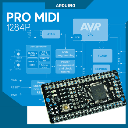
Now we want to return “to the charge” by proposing our latest discovery, which we have called PRO midi 1284P, where the word “midi” is related to the characteristics, which means something between a mini and a mega. The peculiarity of this new Arduino-like board is that it is based on the Atmel/Microchip ATmega1284P MCU. The board is shown in Fig. 1 and, as you can see, is extremely small in size but full of connections to the outside.
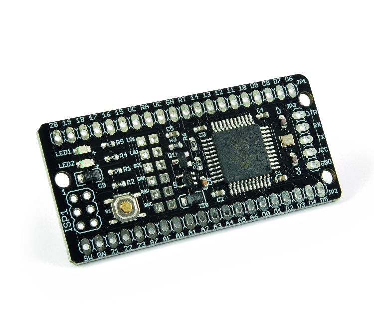
Fig. 1
The board offers, in a very small space, extremely interesting features:
- 16 MHz quartz-generated clock;
- 128 Kbytes of “FLASH” memory (for code);
- 16 Kbytes of SRAM memory (for data);
- 4 Kbytes of EEPROM memory (for data, non-volatile type);
- 3 hardware interrupts (INT0, INT1 and INT2);
- 2 serial ports;
- 1 I2C port;
- 1 SPI port;
- 32 GPIO pins of which 8 with PWM capability;
- 8 analogue inputs with 10-bit ADC;
- 1 analogue comparator;
- 2 8 bits timers (Timer 0 and Timer 2); one of them (Timer 2) is usable as a “Real-Time Counter” with external quartz at 32.768 kHz;
- 2 16-bit timers (Timer 1 and Timer 3);
- “Capacitive Touch Sense” using the Atmel QTouch library.
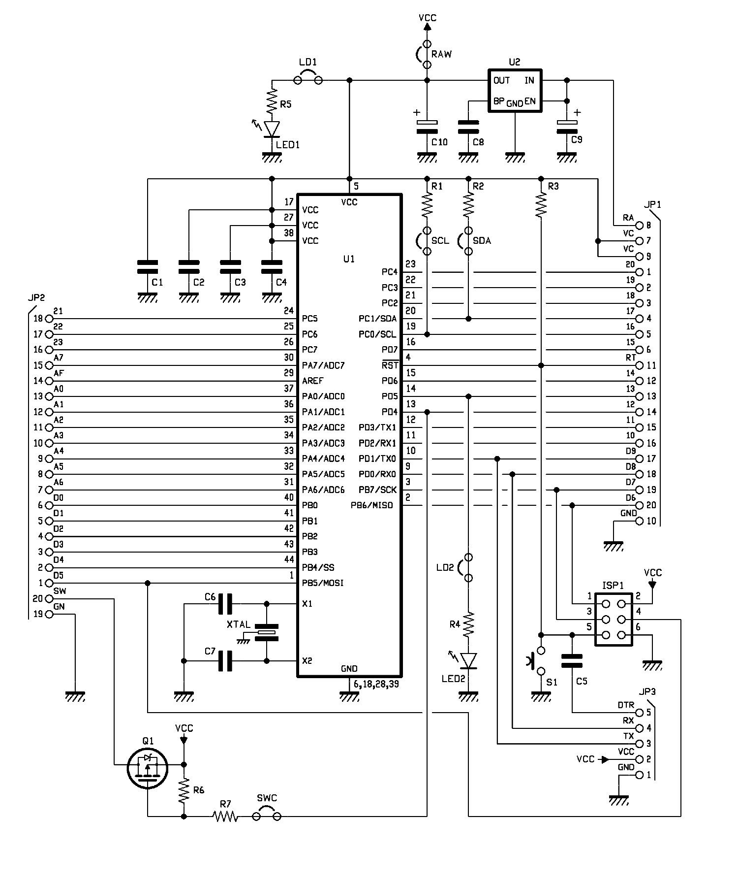
There are also (individually excludable through jumpers cut and reset by the user) these peripherals (Fig. 2);
- Green LED (5V supply, can be excluded by cutting LD1 track);
- Red LED (D13 pin, can be excluded by cutting LD2 track);
- MOSFET (pin D12, excludable by cutting SWC track) to power external objects (e.g. sensors), able to turn on/off loads up to 700mA when using an external 5V supply;
- 7 kΩ pull-up resistors on I²C bus lines (SCL and SDA can be bypassed by cutting their tracks).

Fig. 2
Between each pair of pitches, there is a track that can be interrupted by cutting it.
For those wishing to apply an external power supply other than 5V (however up to a maximum of 12V), the board is equipped with an LDO regulator (excludable by cutting the RAW track) at 5V able to power (given the reduced dissipate power) the only MCU, but not external users.
Basically, in the MCU, is loaded the “Optiboot” bootloader that, through a serial <-> USB adapter to be connected externally (the board is equipped with a 5 pin connector to connect generic “serial <-> USB” adapters) allows easy programming through the Arduino IDE.
There is however a standard ISP connector that allows programming the MCU via an external programmer, such as the Atmel ICE or any other AVR/ISP compatible programmer.
The dimensions of the board are extremely small, similar to those of the “Arduino™ MKR” series, i.e. 56.1 mm x 26.3 mm and also the pinout is partially compatible with some boards of the same MKR series.
The pins marked “TCK (18), TMS (19), TDO (20) and TDI (21)” can be connected to a JTAG programmer/debugger for programming and debugging applications.
On pins TOSC1 (22) and TOSC2 (23) can be connected quartz at 32.768 KHz that, by properly programming the Timer 2 (TC2), can provide the clock to the “Real-Time Counter” that said Timer 2 is able to implement, “Counter” that is able to continue to operate even with the MCU in “Power-Save” mode.
Thanks to the possibility to exclude all hardware that is not needed (LEDs, resistors, MOSFETs, LDO voltage regulator) through the appropriate jumpers, the board is perfectly suited for low-power applications; in fact, excluding all the hardware that is not necessary, the MCU, put in “Power-Save” mode (if desired with the “Real-Time Counter” at 32 kHz active) absorbs only 0.6 µA.
Despite its small size, the ATmega1284P microcontroller has half the Flash of an ATmega2560 (the MCU that equips the Arduino MEGA board) but has twice the SRAM (16 Kbytes) which makes this MCU ideal for those who want to develop applications that use the real-time operating system FreeRTOS; in such applications, in addition to the large memory for the code that the ATmega1284P provides, 128Kbytes, it is essential to have a large SRAM, since each task that is created, still needs its own space for the stack and for its system variables.
BLOCK DIAGRAM OF THE ATMEGA1284P
As already exposed in previous paragraphs, the core of the board Pro Midi 1284P is the microcontroller Atmel / Microchip ATmega1284P, understand the characteristics of which is more immediate by casting a glance at Fig. 3 which shows the block diagram “functional”. In it we see peripherals, modules and registers, in addition to the particular clock generator.
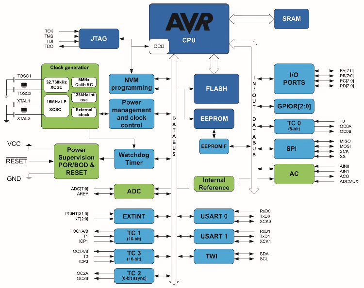
Fig. 3
Programming the ATMEGA1284P with Arduino IDE
As already mentioned, the board can be programmed in the Arduino IDE environment.
To do this, the appropriate “core” must be added to the IDE.
Open the IDE “preferences” and add the following line in the field “Additional Boards manager URLs”:
https://mcudude.github.io/MightyCore/package_MCUdude_MightyCore_index.json
After that, you have to go to the Tools menu, give the command Card Manager and select, from the submenu that opens, as the card the:
MightyCore
>Atmega1284
Once the tab has been selected, it is necessary to select from the options that appear:
Clock: “External 16 MHz”
BOD: “disabled” (o il livello di tensione da voi scelto)
Compiler LTO: “LTO disabled”
Variant: “1284P”
Pinout: “Standard pinout”
Bootloader: “YES (UART0)”
In this way you have configured the IDE to use the board and, once you have selected the correct serial port (the one created by the USB <-> serial adapter), you will be able to load the code directly via bootloader.
To facilitate the writing of the code, a “.h” module is provided that can be included in the project and that defines, in a mnemonic way, a series of “pins” present on the “PRO midi 1284P” board. The name of this module is “ProMidi1284P.h” and can be downloaded from the download area of the magazine and contains the definitions summarized in Listing 1.
Listing 1.
/*
Pins definitions addendum for ProMidi 1284P
Guglielmo Braguglia - May 2019
*/
#ifndef Pins_ProMidi1284_h
#define Pins_ProMidi1284_h
#ifdef LED_BUILTIN
#undef LED_BUILTIN
#endif
#define LED_BUILTIN 13
#ifndef SWC_BUILTIN
#define SWC_BUILTIN 12
#endif
#ifndef NOT_AN_INTERRUPT
#define NOT_AN_INTERRUPT -1
#define digitalPinToInterrupt(p) ( (p) == 10 ? 0 : (
(p) == 11 ? 1 : ( (p) == 2 ? 2 : NOT_AN_INTERRUPT ) ) )
#endif
#define PIN_D0 (0)
#define PIN_D1 (1)
#define PIN_D2 (2)
#define PIN_D3 (3)
#define PIN_D4 (4)
#define PIN_D5 (5)
#define PIN_D6 (6)
#define PIN_D7 (7)
#define PIN_D8 (8)
#define PIN_D9 (9)
#define PIN_D10 (10)
#define PIN_D11 (11)
#define PIN_D12 (12)
#define PIN_D13 (13)
#define PIN_D14 (14)
#define PIN_D15 (15)
#define PIN_D16 (16)
#define PIN_D17 (17)
#define PIN_D18 (18)
#define PIN_D19 (19)
#define PIN_D20 (20)
#define PIN_INT0 (10)
#define PIN_INT1 (11)
#define PIN_INT2 (2)
static const uint8_t D0 = PIN_D0;
static const uint8_t D1 = PIN_D1;
static const uint8_t D2 = PIN_D2;
static const uint8_t D3 = PIN_D3;
static const uint8_t D4 = PIN_D4;
static const uint8_t D5 = PIN_D5;
static const uint8_t D6 = PIN_D6;
static const uint8_t D7 = PIN_D7;
static const uint8_t D8 = PIN_D8;
static const uint8_t D9 = PIN_D9;
static const uint8_t D10 = PIN_D10;
static const uint8_t D11 = PIN_D11;
static const uint8_t D12 = PIN_D12;
static const uint8_t D13 = PIN_D13;
static const uint8_t D14 = PIN_D14;
static const uint8_t D15 = PIN_D15;
static const uint8_t D16 = PIN_D16;
static const uint8_t D17 = PIN_D17;
static const uint8_t D18 = PIN_D18;
static const uint8_t D19 = PIN_D19;
static const uint8_t D20 = PIN_D20;
static const uint8_t PIN_RX0 = PIN_D8;
static const uint8_t PIN_TX0 = PIN_D9;
static const uint8_t PIN_RX1 = PIN_D10;
static const uint8_t PIN_TX1 = PIN_D11;
static const uint8_t PIN_SCL = PIN_D16;
static const uint8_t PIN_SDA = PIN_D17;
static const uint8_t PIN_SCK = PIN_D7;
static const uint8_t PIN_MISO = PIN_D6;
static const uint8_t PIN_MOSI = PIN_D5;
static const uint8_t PIN_SS = PIN_D4;
#endif
For those who prefer other development environments, we point out that the board is fully programmable using the Microchip IDE MPLAB X both with the XC8 compiler (which currently only supports ‘C’ code) and by installing the special “AVR Toolchain” (which also allows loading ‘C++’ code). The advantage of using such an environment is that, by connecting the board to a JTAG programmer/debugger supported by MPLAB X, it is not only possible to program the MCU, but it is also possible to do real debugging both by inserting breakpoints and by executing the code in step-by-step mode.
Using “ISP” programming, or “JTAG” programming, with the help of an external programmer, the “bootloader” is cleared. If you want to restore the board to the original conditions, with the “bootloader” and the “blink” program preloaded, simply download from the download area of the magazine the file named “ProMidi.hex” and, again with the help of the external programmer, load this file on the board.
If the values of the “FUSE” have also been altered, they can be restored to the following original values using an external programmer:
Low = 0xD7, High = 0xDE, Ext = 0xFD.
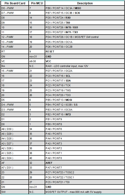
Regarding pinouts, Table 1 provides detailed information about each pin that the Pro Midi 1284P board provides.
Table 1
MOSFET ON/OFF CIRCUIT DIAGRAM
As mentioned, the Pro Midi 1284P is equipped with a switch, based on a MOSFET FDN360P, that is able to turn on and off loads connected between the SW pin of the board and the GND pin. This transistor allows to control of loads with maximum absorption of 800mA and only in the presence of an external stabilized power supply capable of providing the necessary current (so when the board is powered through the RAW pin). It is controlled by pin D12 (Fig. 4).
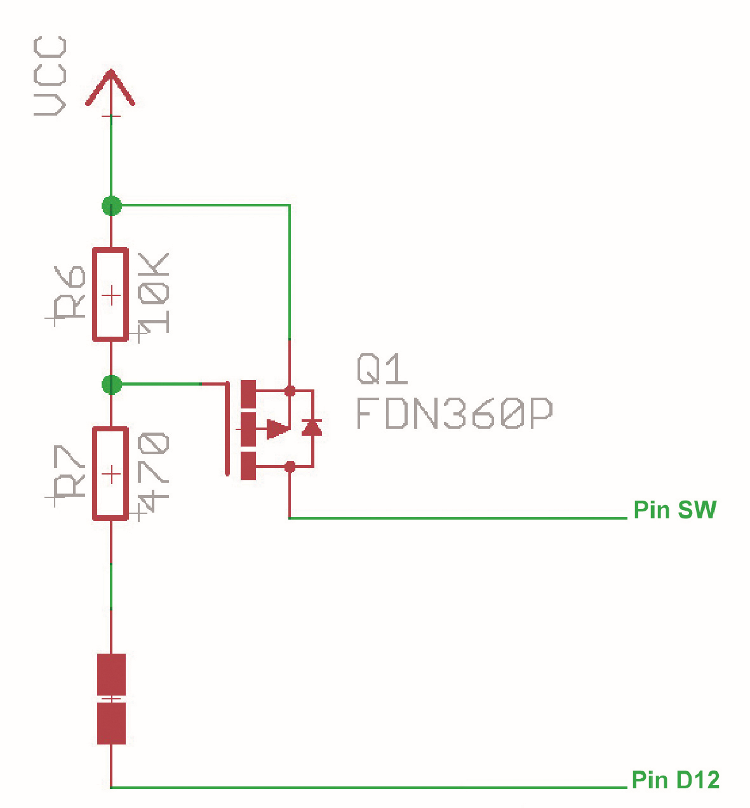
Fig. 4
BOM:
R1, R2: 4.7 Kohm (0603)
R3, R6:10 Kohm (0603)
R4, R5, R7: 470 ohms (0603)
C1, C2, C3, C4, C5: 100 nF ceramic (0603)
C6, C7: 18pF ceramic (0603)
C8: 470 pF ceramic (0603)
C9: 10 µF 10V tantalum
XTAL: Quartz 16 MHz
U1: ATMEGA1284P-AU
U2: MIC5205-3.3YM5-TR
LED1: Green LED (0805)
LED2: Red LED (0805)
Q1: FDN360P
S1: Microswitch
Various
– 5-way male strip
– 20-way male strip (2 pcs.)
– 2×3-way male strip
– Printed circuit S1493 (57×27 mm)
CONCLUSIONS
The Pro Midi 1284P that we have presented in this article is the ideal board for those who, while wanting to remain in the Atmel AVR family, needs a large amount of both Flash memory for its code and SRAM memory. Precisely the large amount of the latter (it is well 16 kB), makes it the ideal board for those who want to develop applications with the help of the operating system “real-time” FreeRTOS ™, while maintaining the simplicity of programming in an Arduino environment thanks to the aforementioned “MightyCore“, installable from the IDE add-in card manager.
The extremely small size allows then the insertion in extremely compact equipment and, thanks to the possibility of eliminating the “superfluous” (LEDs, pull-up, etc..), even at very low power consumption (it is a few microamps).
FROM OPENSTORE

thanks to the possibility of eliminating the “superfluous” (LEDs, pull-up, etc..), even at very low power consumption (it is a few microamps).
thanks for the valuable post
Looks like a great idea and product, but the heading of this article almost caused me not to open it. I thought it was about the MIDI music interface.