
We present a caterpillar robot based on Arduino Uno, remotely controlled through a Play Station 2 wireless controllers.
Since we are not insensitive to solutions making life easier, we have considered the idea of creating and proposing something that could help us avoiding the cold and fatigue of using the usual manual shovel and at the same time, we opted not to replicate something already available but a new fun and technologic device. We therefore decided to start developing a Snowplow Robot, remotely controlled, proudly showing a robust mechanics and fine electronics all implemented with cards easily available on the market.
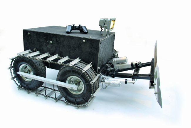
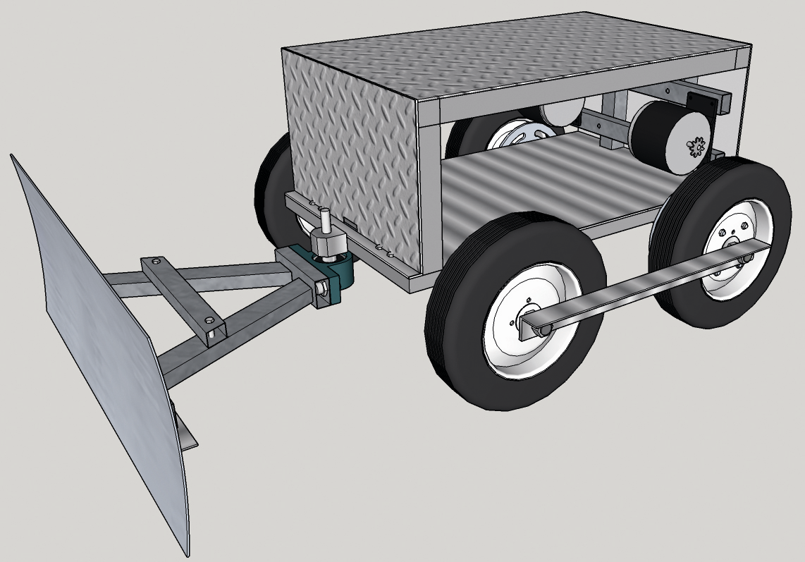
The result is a miniature version of a true snowplow, caterpillar tracks, with blade and light projector mounted on top to light the way in the dark; everything is controlled by a remote control from the PlayStation 2. Let us see how our caterpillar robot is assembled, starting from the mechanics and then describing the electronics and firmware that is necessary.
Mechanics
On the mechanical side, the robot consists of a snowplow frame that supports a motorized blade (that can be raised and moved) and the traction system: electric motors, wheels and tracks.
The frame

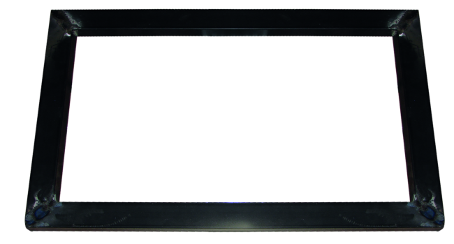
Initially it was thought to assemble the entire structure creating an aluminum tubular frame held together by corner brackets, but given the high mechanical stresses and the robustness required, we decided to use for the base four tubular iron (rectangular section) welded together, thus obtaining a rectangle by 600×375 mm.

As a base for the various mechanical components, we used an aluminum plate 3 mm thick 600×375 fixed on the iron frame. Two aluminum profiles vertically mounted (30×30 mm section and 190 mm length), plus two horizontal (30x30x580 mm long side) and two more (30x30x375 mm short side) were used as a skeleton on which we will apply the outer cover of the robot (made using 5 panels aluminum 3 mm thick); to fix the struts to the base, we must practice a hole in their section (8MA), then threaded. Two “L” aluminum brackets shall be fixed always on the front of the frame, and serve as a support for the two linear actuators that allow the blade to rotate right and left.
The traction system
The movement of the snowplow is granted by four trolley wheels, fitted with tires and hub provided with ball bearing with a hole of 16 mm diameter; each wheel has an outer diameter of 26 cm and about 8.5 cm wide tire. Easily available in many DIY centers, these wheels are capable of bearing (individually) a weight of 150 kg, for a total of 600 kg, much more than what we need for our robot. For the wheels axles we have used 16 mm diameter threaded bars, 63 cm long, passed through the aluminum supports and there blocked, caring that those rods protrude equally on each side. The supports are fixed to the lower base of robot’s frame.

To lock the wheels at the right distance (the side facing the support) you can opt for two solutions; nut and locknut, or, as in our case, directly weld a nut on the threaded bar. For this solution, once that is done you need to put a nut (16 MA) in threaded rod, screw it until it get to about 7 cm from the support bar, check precisely the measure and then weld it. The same applies to the other side and the other bar.
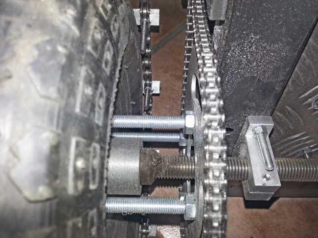
To mount the gear on each wheel, you have to remove the four original bolts and derive four holes of equal diameter, matching those of the respective wheel; to position the holes with precision it is convenient to create a cardboard template matching the distance between the holes on the wheels.

Drill the gears and then put the four 8MA 100 mm long in and screw a nut lock to secure the bolt to the wheel rim; then put another nut (or nut and lock nut) at a distance of about 72 mm from the nut screwed into the inner side of the rim. Now you can apply the worm wheel, centering the respective holes and screw tight with four nuts. Having done this, you can mount the wheel: if everything is correct, you will have the nuts of the gear at a maximum distance of 10 mm from the frame.
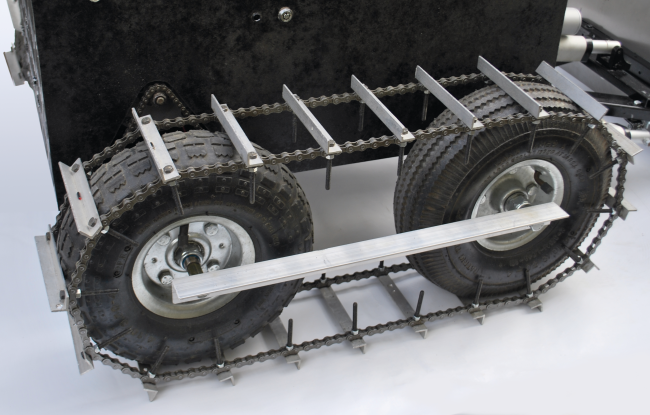
On each axle, you must enter the lock nuts 16 MA. Externally, the two wheels are spaced and held in tension by an angular bar of aluminum 30×30 mm, 2 mm thick and should be fixed by a bolt in the center of the threaded bar. When we lowered the blade to shovel we realized that it was necessary to increase adherence using caterpillar tracks (or suitable wheels, such as those of tractors), but we decided to find an alternative solution.

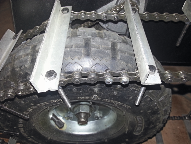
Inspired by the various solutions found on Internet and adapting them to our needs, we have created the tracks by ourselves using four packs of bicycle chains 1/2 “x1/8” with 114 links each (two per side, for a total of 120 links, corresponding to a length of about 166 cm), 40 aluminum corner (mm) 120 12×12 long with a thickness of 2 and 80 5MA bolts 50 mm long and relative nuts. The angular aluminum brackets, spaced 8 cm center to center from a bolt, are needed to hold together and parallel the two chains of each pair constituting a track (wrapped around the relative pair of wheels) and are responsible to obtain the right grip on the snowpack. On each corner, you must drill two holes in which you must insert two bolts 5MA x 50 mm and secure them to the chain, preventing it from slipping to one side or the other.
To match the wheels to the motor pinion MY1016, it was necessary to procure two short pitch chains (like those of electric scooters or mini-motorbikes), to mount two gears of diameter 155 mm to 76 teeth on the driving wheels and space them of about 35 mm from the wheel (the inside of the tire) with 4 bolts 8MA x 100 mm. To fix the engines we used brackets, realized from two rectangular bars of iron (mm) 30×20 375 long and drilled. Starting from the outside, the first hole is approximately at 14 mm, while the second is at 42 mm from the first; this distance corresponds to the holes of the engine (the narrowest part of the motor bracket).
On the bar we drill two holes, at 110 mm from the outside and at both sides, required to fix the two vertical bars 190 mm. The same perforation was made for the second bar. The two vertical bars 19 mm, once welded to the base of the frame, have been drilled at a distance (from the base of the frame) of about 44 mm for the first hole (slot shaped) and 139 mm for the second hole (always slot shaped). At this point all that remains is to fix engines, directing the pinion to the outside and ensuring that it is in line with the gear wheel.
Blade

The most complex mechanical part is the blade support and its mechanism. To make the blade we used a sheet of rectangular steel 650×250 mm, 2 mm thick, which we then slightly curved (above and below, the long side) to facilitate the snow shoveling.
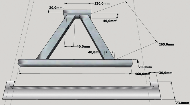
For the mechanical structure that supports the blade and allows it to move, we used:
- a box-shaped iron frame 30×20 mm, 265 mm length, cut off at the end with the required angle
- one iron square rail 40×20 mm 13 cm long
- a rectangular profile 30×20 mm 46 mm long
- an interlocking truss 600 mm long (used for shelves and available in DIY shops), with a bearing support by 16 mm
- two boxes 40×30 mm long 26,5 cm cut end at the demanded angle.

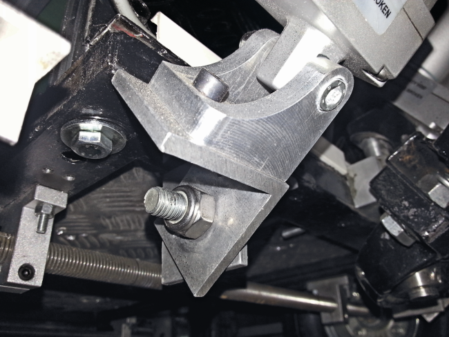
We then made an aluminum rod 11 cm long (12 mm, except in the first 5 mm where it is 14 mm) to be inserted into the 12 mm bearing; in its upper part it has been drilled a 5 mm hole, threaded, to fix by means of a bolt 5MA the bracket for the linear actuator which allows to raise and lower the blade. The second bracket is fixed to the center of the bar with length 265 mm. To rotate the blade to the right and left, we used for each side two L-brackets aluminum 50×50 mm, 40mm width and 5mm thick, drilled and screwed by inserting a washer between the two. A pair of “L-bracket” was fixed, by means of two bolts, in the lower part (left side) of the frame and the other to the right.

The linear actuator is fixed to one end of the L-bracket while the other end was fixed on the triangular structure of the blade, for both sides.
Before drilling and secure the three linear actuators to the blade triangle, you have to take the two linear actuators to move it to right and left, apply 12 VDC to one of the two in order to have the maximum extension, while the other must be fully pulled back. Now you must wire the power supply wires of the two actuators in order to have the positive of the 1st actuator connected with the negative of the 2nd and the negative of the 1st to the positive of the 2nd. Then feed the wired pair of actuators and switch off the tension when they reach the same extension. Now you can attach the brackets of the linear actuator (cod. SUPPLACT) to those of the two side-actuators (on the back).

The bracket must be fixed to the pair of aluminum “L-brackets” (the one with the interposed washer), previously fixed on the front lower frame. Now you can position the part of the actuator arm near the triangle of the blade, fix a small “L” (will serve as the anchor) and take accurate measures before drilling permanently. All that remains is to place also the central actuator, fixing the bracket on the central pivot of the bearing and then securing it (after inserting the specific bracket also on the part of the piston) on the central area of the triangle of the blade.

The interlocking crossbar is fastened to the horizontal bar of the blade triangle, drilled and fastened. The blade steel, properly bended, should be placed on the crossbar to mark the drill holes.
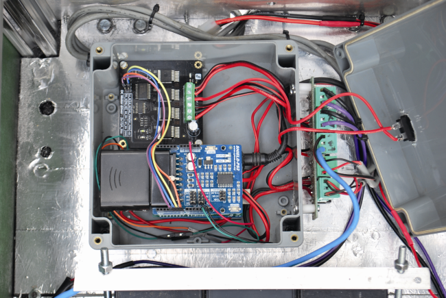
Electronics

Electrical and electronic part of the snowplow is based on Arduino Uno, hosting three shields and interfacing with:
- Motor driver;
- relays circuitry RELAY1CH;
- DC/DC converter step up STEPUP30V.
The shield mounted on Arduino are the motor shield to control the three linear motors that manage the movement of the blade and the PS2SHIELD, which allows you to interface with the PlayStation 2 (PS2); the latter requires the RX-PS2, which is a 2.4 GHz radio receiver for sending/receiving specific commands from the aforementioned console.
The wiring diagram of the robot is what you find in these pages; the power source is made by a series of two lead gel batteries by 7.2 Ah: we take the 12 V from the mid-point connection of the two, while between the negative and the positive of the series we take 24 volts. A switch (125V, 2×15 ampere) controls the two supply lines.
With 12 volts, we run Arduino, which will power the shields through its pin-strip; a LED (internally mounting the limiting resistor) will indicate when Arduino is running. The 12 volt directly from the battery stack is also feeding the power section of the motor shield. In fact, since the absorption of the three linear actuators (cod. LACT2) is high, it is not advisable to take the 12 V from Arduino: you opt for the external power supply to be provided to the appropriate PWR terminal. To use the external power supply, you must move the jumper (on the shield) near the terminal, between the central and the EXT. The management of the shield requires a special library for Arduino, supplied with the component. Each linear actuator is composed by a 12 Vdc gear motor using a worm screw to move a shaft back and forth along its length (maximum excursion of 5 cm). The actuator has a dynamic load of 50 kg and a maximum speed of 1.3 cm / s. It is able to support up to about 250 kg, when not moving, and the torque ensures the maintenance of the position of the shaft even in the absence of power. Two limit switches provide the engine to stop when it reaches the maximum extension and contraction, while the diodes allow reverse direction after reaching the limit point. The actuator is made of metal and is sealed to protect it from dust and water (IP63 rated).
Let us now turn to the 24 volts supply line, which is feeding the power part of the snowplow, which are the traction and the projector (optional) sections: the first is based on the motor driver, to be connected with four wires to the same number of Arduino digital lines.
The motor driver is a double bridge power driver capable of driving two brushed motors continuously with a voltage of max 35 VDC and a current of 15 A (each). By interfacing with Arduino and using only four digital I / O (2 PWM), you can choose the rotation direction and speed of the motors. The circuit has four control pins, four LEDs that indicate the rotation direction of motors, two pins for the board power supply (5 Vdc) and two aluminum heat sinks located in the rear of the printed circuit, necessary to dissipate the heat generated during operation at full power. For the management of the driver by Arduino, the manufacturer provides a special library. The output terminal blocks allow you to connect the two engines, to be connected as indicated by the diagram (do not invert polarity, otherwise the tracks will run in reverse!) using cables with a section of at least 1.5 sq. mm.
About control inputs, it should be respected the connection between Arduino and the controller connector pitch 2.54; correspondence that is needed when using the library provided by the manufacturer and our firmware: if you edit them, you have to revise connections. Remember that DIR are the logic levels to set the motors rotation direction and PWM are the PWM signals to command the power drivers.
To identify the controller connector contacts it’s sufficient to refer to the silkscreen visible next to it on the component side of the circuit board.
In addition to the engine controller, the 24 volts will power the section of the LED projector, you can mount or not; if mounted, respected wiring indicated and remember to take the positive 24 V from the relay card (cod. RELAY1CH). The latter houses a relay and the respective drive transistor controlled by Arduino through the Digital I/O 13; Arduino also powers the card, by means of the +5V and ground (GND).
A relay allows turning on and off the projector, targeting action on the corresponding circuit.
The projector is designed to operate at 220 Vac, however, since this voltage is not available on the robot, to avoid using an inverter we modified the projector by opening it, removing the AC / DC and bringing the two wires of the power LED directly to the output of the converter DC / DC (cod. STEPUP30V); the latter is a switching converter with adjustable output voltage, which should be tuned in order to provide to the LED a current such as to make it work at about 10 watts. Usually this is achieved at about 30 volts. However remember that the power is given by the product VxI, (current by voltage, in watts is obtained if V is in volts and I in amperes), then to 30 V, the current consumption should be just under 340 mA. Although the group of LEDs is internally protected from overcurrent, the STEPUP30V has a limitation of the output current to 2A so it can be useful to replace it with a DC / DC equipped with output current limiter; a good example is available on the website www.futurashop.it as STEPUP30VADJ.
Receiving data from the remote control is the job done by the shield PS2SHIELD, for which the manufacturer makes available the specific library. The shield performs the receiving and decoding of the command; the radio part is left to the RX _PS2, which is inserted into the related connector.
The last thing to note is the photoresistor, used by Arduino to detect the ambient lighting and to control the board RELAY1CH so the LED projector is turned on; the component is fed to the voltage divider by a resistor of 10 kOhm (1/4 W) and is read from the analog input A0 Arduino. The 5 volts are taken from Arduino 5V.
This light sensor does a simple thing: in good lighting conditions, the resistance of the photoresistor is low and the voltage read by the ADC of Arduino microcontroller is low and does not trigger the relay board; darkness instead, increases resistance a lot and the ADC reads a voltage close to 5 volts, which causes the projector to switch on.
For the hardware part that’s all: in a coming post episode we will share and explain the Arduino sketches.

http://www.open-electronics.org/open-source-boats-the-opportunity-to-build-a-foundation/
[…] To see how to assemble the caterpillar robot, check this link. […]
but you could just some junk rc gear? its not really arduino if its just a big rc car..
it’s “open source”
nice ! what is refence of your actuator please
https://store.open-electronics.org/index.php?_route_=LinearActuator_2
can you provide a makor parts list needed – electrontcs at least…
see the other post
[…] Here comes the open source Snow Plow RobotPosted 1 month ago […]
Hi Vittorio! We would like to feature this project on EEWeb.com. If you are interested, kindly drop me a message on my business e-mail: cexclamador.eeweb@gmail.com. I’ll be looking forward to your response! Thanks.
I have sent you an email about 10 days ago, but I have not received your reply.
I look forward to receiving your reply
Vittorio
Hi Vittorio,
Unable to send you my reply because it bounces back. Attempted to send it 3 times already. Please provide another email address.
Thanks!
try this: vittorio.loschiavo@fastwebnet.it
[…] recently presented our Open Source Snow Plow Robot project to Boca Bearings Innovation Competition and it has been selected and you can now vote […]
[…] Source: Here comes the open source Snow Plow Robot | Open Electronics […]
Hi, I love your open project! Could you specify which motors you have used with DRI0018 driver?
And what is the total weight of the robot.
This one
https://store.open-electronics.org/index.php?_route_=MY1016-24VDC
Thanks
hi, i’m planning on doing something like this for my capstone and i was wonderng if it is possible if you have and links or guides for the code, as well as this ps2sheild as it seems arduino no longer sells it. please email me if you can possiable help
https://store.open-electronics.org/index.php?_route_=PS2SHIELD
hi this project is good for my project we want six degree of freedom for plow, is it possible to do it?
[…] It’s January, which for many of you means winter is well underway. Whether you simply hate the freezing cold or always seem to throw your back out while shoveling, what if there was a machine that could take care the tedious task for you without ever having to step foot outside? This is exactly what Boris Landoni decided to do by devising his own open source, remote-controlled Snow Plow Robot. […]
Please provide sourcing for the gears (sprockets). Also, what is meant by “apply the worm wheel”?
Ciao, mi invieresti il codice di arduino per il modulo ps2shield ? grazie signorgallo95@gmail.com
[…] Here comes the open source Snow Plow Robot […]
[…] more info about this project. […]
Excelente Projeto tanto mecânico com a integração com PS2.
Carlos Bruni
Salvador Bahia Brasil
can i get the arduino code for this one