Up to 200 numbers can be stored and enabled to control the relay, which allows people to use the gate opener not only in big condos and residences, but also in companies and all those other contexts in which many users are likely to need to have access. In order to avoid using SMSs, which are not the best method when storing many phone numbers in that they entail spending money (SMSs are expensive…) and using a small and impractical cell phone’s keyboard, we have devised a software program to be used on a PC, to which one can connect the circuit by adding a TTL/USB converter module on a special serial interface connector.
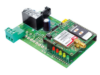
On this page, you will find the assembling directions along with the list of the components necessary to create a gate opener using the same printed board used to build the entire remote control; as you can see, the printed circuit is less “populated” than before, as many of the scheme components appearing in our previous issue are no longer necessary. As a matter of fact, in order to create the gate opener function, all you need is a microcontroller and its surrounding components, in addition to a small board with the GSM module and its antenna, a relay, a terminal board to connect all the contacts, the LEDs and power plug. In the list of components found on this page, those components that need not be assembled are marked with a dash.

Top Layer
PARTS LIST:
R1: 0,1 ohm 1W (1206)
R2: 2,2 kohm (0805)
R3, R20: 1 kohm (0805)
R8: 330 ohm (0805)
R9: 4,7 kohm (0805)
R10: 10 kohm (0805)
R7, R8, R13, R14, R17: 330 ohm (0805)
R15, R16: 1,5 kohm (0805)
R21: 2,2 kohm (0805)
R4, R5, R6, R7, R11, R12, R18, R19: unused
R22, R23, R24, R25, R26, R27: unused
C1, C4, C7, C13: 100 nF multilayer (0805)
C2: 1000 µF 25 VL electrolytic
C3: 100 pF ceramic (0805)
C5: 100 µF 16 VL electrolytic
C8, C14, C15, C16: 470 µF 6,3 VL tantalum (CASE-D)
C11: 100 µF 16 VL electrolytic
C6, C9, C10, C12, C17, C18, C19, C20: unused
Q1, Q2: unused
U1: MC34063AD
U3: 24FC256-SN
U6: PIC18F46K20-I/PT
U2, U4, U5, U7: unused
D1, D3: 1N4007
D2: 1N5819
D4: unused
T1: BC817
T2: unused
LD1: LED 3 mm red
LD2: unused
LD3, LD4: LED 3 mm yellow
LD5: LED 3 mm green
L1: Inductor coil 22 µH
RL1: Relay 5V 1 one way
RL2: unused
P1: unused
F1: Fast fuse 2 A (1206)
Miscellaneous:
– Screw connector 3 poles
– DC plug
– Female strip 6 poles
– Female strip 3 poles
– Female strip 16 poles
– Female strip 4 poles 90°
– PCB
For PC programming, and in order to take advantage of the relative software, you can use the TTL/USB converter module shown already assembled in the picture, in a special four-pole pin-strip, at the top, to the left of the small GSM board.

Programming Interface (TTL/USB Converter)

what codes shoud i put?? i need tips and proceedure..pls help this is important for our project in school….thank you…
Hi drix, now you can download the gate control firmware in this page
where can i get the complete gerbers or pcb layout pdfs?
pcb?