[youtube id=”eINAuYg-ftM” width=”620″ height=”360″]
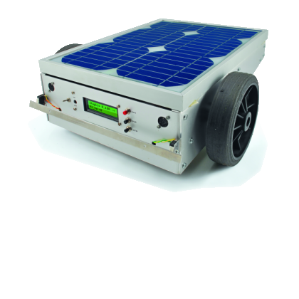
This robot will mow the grass of your garden, staying within a defined area, avoiding all obstacles and working in complete autonomy, automatically charging itself with a solar panel.
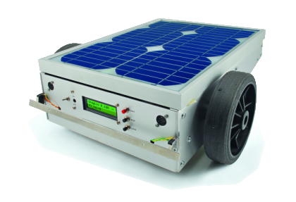
In this post we present a robotic lawn mower, powered with solar energy and able to operate just with the clean energy from the sun; this one is a great difference from the commercial projects having a robot in need of a charging station connected to the electrical grid. When designing a lawn mower powered by solar energy, it is essential that most of the energy comes from the sun, and of course the ultimate result would be obtained if solar energy were enough to completely power up the robot: this one is however an objective that will be very difficult to obtain, given the low efficiency of existing solar panels. In our project the whole surface of the robot is destined to solar panels, acting also as a cover: only the sides have been left free, and anyway they wouldn’t play a decisive role in supplying energy. Obviously, this choice poses a serious constraint to the rest of the project, since in this way we already defined the maximum power available.
We have to consider that solar power will not always be available, as many garden areas are often in shade, or anyway not directly hit by the sun, so we have to take into account considerable losses of power. These losses can be made up only if the robot has an accumulator capable of supplying energy when it is lacking from the sun. In this situation the battery works as a buffer, accumulating energy when it is plenty, and supplying it when the robot, on the contrary, is in shade. From this point of view lead batteries are the most suitable ones, but nothing forbids us to use batteries that can be performing more in terms of weight and capacity, like lithium ones. In full sun, the solar panel is capable of recharging the internal battery with a current at about 0,6A, totalling about 8W, well under the power used by even the most efficient electric lawn mower, powered at 220Vac. This makes us understand already that a product like the one we’re describing in these pages cannot substitute a manually operated lawn mower completely, as this last one should be used every now and then, when the grass is too tall. Rather, the robotic lawn mower can be used for a continuous and steady mowing of the lawn.
This solution also offers a further advantage, since the continuous mowing ensures that the grass is always young and soft, and as it is cut in very small pieces it is due to decompose itself in a short time, thus serving as fertilization for the lawn. You shouldn’t expect the grass that has been cut to be gathered: on the contrary, it will deposit itself among the grass blades that have just been cut.
For this kind of usage, less power is needed, and can be easily managed with a battery powered system. The weak power in play convinced us to choose a traction and a cutting engine with reduced power. Probably, they might not completely suit the needs of our readers, who may anyway pick up the engines and the structure they prefer, depending on their budget and personal exigencies. To define the cutting zones in a lawn, the underground wiring system proves to be at the same time simple, accurate and reliable. It is also the best system to define the work area of the robot.
Everything is based on the usage of a simple electric wire, laid on the ground or a bit under it, and connected to a control unit powering the wire itself with an alternating electric signal at about 10 V and a frequency of 34KHz. In the lower part of the chassis of the robot two small reels are installed, one on the right side, the other on the left side, both referring to an electric circuit formed by a capacitor in parallel. The circuit formed by the parallel inductance and the capacitor is called parallel resonating circuit and is calculated so that the tension at its ends, induced by the external magnetic field, is at a maximum when the magnetic field varies with a frequency of 34KHz.
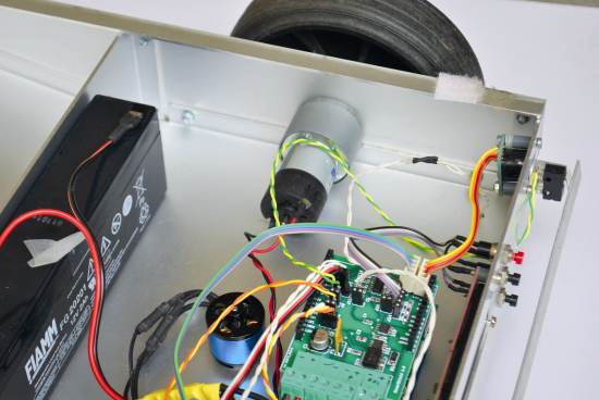
Let’s move now to a more detailed description of the electric part adopted by this project. The most important innovation is the adoption of Arduino as control board, allowing u sto obtain a project that is a bit more user friendly and more hackable, even by the less experienced ones. To allow the maximum usage flexibility, instead of realizing an ad hoc electronic board we thought to realize a specific shield.
This choice also determined a disadvantage, as for the absorption of current when the board is in stand-by mode, an eventuality that might happen during the night, with the robot remaining without a power source. In this situation the internal battery will have to face a prolonged powering of the Arduino board and shields.
Concerning the management of engines, as for the traction, we calculated the usage of a commercial shield, the only one commercially available to allow the modification of the assignation of the control pins; as for this use Tab. 1 to correctly assign the pins. The engines’ shield allows to manage two engines for a total maximum absorption of 2A each, ensuring enough power for the traction. Obviously, nothing forbids us to use other kinds of drivers for the engines, allowing an increase in power; the only important thing is that the driver has available two control signals for each engine, one to define the direction, the other one for the PWM signal, needed to control speed.
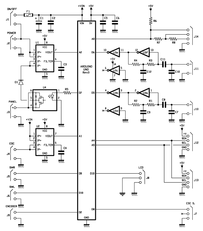
The shield has been designed using recent components with specific functions, thus the need to use high-integration SMD components, that allowed to fit everything into a shield that is compatible with Arduino UNO. The section being destined to the reading of the underground wiring is based upon an integrated circuit containing six NOT gates of the CD4069 type. With this integrated circuit we simply have to amplify and square the weak signal at the heads of the parallel resonating circuit. Even in this project we calculated the possibility to activate or deactivate the solar panel; for this purpose, we relied on the integrated circuit ASSR 1611, a solid state switch that is controlled by an opto-isolator. If the buffer battery being used is of the lead kind, there is no need to detach the panel, as over charge is well supported by this kind of batteries, if you however use the more modern lithium batteries it is of the essential that the charge is suspended once the limit voltage is reached, otherwise you might incur in battery damage or, in the worst of cases, in an explosion.
Two integrated circuits named ACS712 allow the measuring of the current supplied by the solar panel and of the current absorbed by the cutting engine: the version with a range of 5 A seemed more than enough for us.
These integrated circuits use the Hall effect technology to supply (as output) a tension that is proportional to the circulating current on the power circuit, mantaining a galvanic separation with the output stage. The possibility to measure the solar panel’s current will be basic to detect the most suitable area to recharge the battery. When running, the level of current supplied by the panel is in fact stored, and the data is used again when the lawn mower will have to find a recharge zone, in the case the battery was close to low. The robot doesn’t know the real atmospheric situation (sunny or cloudy) nor the presence or not of zones in shade, and it doesn’t even know if it is darkening: it will simply look for a sufficiently luminous area, in respect to the maximum luminous intensity, as detected during the last work session. The measure of the current absorbed by the cutting engine will be fundamental to know the effort during the cut and basic to calculate when to stop the cut in an anomalous situation.
To complete the discussion about the shield, we have to notice the diode D1, which is needed to avoid the tension of the battery ending on the photovoltaic panel, in the case it was lowly lit; and two connectors, needed to make the I2C BUS available.

Three buttons for generic use have also been designed, and they are connected through a resistor network to the analog input A0; all of the digital pins have in fact been occupied. One entry is used by a reed sensor that is placed very close to the rear pivoting wheel, and is operated by a small magnet which is inserted in the same wheel at each rotation. With this sensor it is possible to determine if the robot is moving regularly or if one or more wheels are locked or moving in vain.

We added two digital inputs, to whom you may connect the mechanic switches for obstacle recognition on the front; this in addition to the proven ultrasonic sensor, that are connected to the I2C BUS and detect objects in the front.
The ultrasonic sensors, though behaving extremely well, might be fooled by objects with a particularly small surface, such as a metal net, or by some very irregular surfaces such as a bush.
As for lawn mowing, we relied on a brushless motor, used in the field of aeromodelling, who was coupled to a cutting blade obtained by combining two cutter blades.
We’re talking about a 200W engine, that is however used for not more than 20%. The engine control is assigned to an ESC (electronic speed control), of the kind used in model building, and is operated with a simple PWM signal, easily managed with Arduino, since it is already present with the relative function in the system library.
To measure the tension at the heads of the battery we shall use the voltage divider already there in the motorshield. It is however needed to modify the track bringing the tension in output from the divider from pin A5 to pin A3, so that pins A4 and A5 are available for the I2C BUS. The two digital lines D0 and D1 are used to communicate with the PC, but once Arduino has been programmed, they can be used for communications with other peripherals such as GPS or Bluetooth.
Tab. 1 Mower Shield pin connect
| Pin Arduino | name | Description |
| A0 | Button_pin | Push button |
| A1 | ICut_pin | Motor cut current |
| A2 | IPanel_pin | Solar panel current |
| A3 | VBat_pin | Battery voltage (from motorshield_FE) |
| A4 | SDA_pin | I2C BUS |
| A5 | SCL_pin | I2C BUS |
| D0 | RXD_pin | GPS or bluetooth |
| D1 | TXD_pin | GPS or bluetooth |
| D2 | Encoder_pin | Encoder pivoting wheel |
| D3 | PWMA_pin | PWM motor A motorshield_FE |
| D4 | DIRA_pin | Direction motor A motorshield_FE |
| D5 | BWFR_pin | Buried Wire Fence Right |
| D6 | BWFL_pin | Buried Wire Fence Left |
| D7 | Panel_pin | ON/OFF pannel |
| D8 | ESC_pin | ESC cut motor signal |
| D9 | SWOL_pin | Obstacle switch Right |
| D10 | SWOR_pin | Obstacle switch Left |
| D11 | PWMB_pin | PWM motor B motorshield_FE |
| D12 | DIRB_pin | Direction motor B motorshield_FE |
| D13 | LCD_pin | Serial LCD |
The hardware is now quite complete and the shield does his job extremely well, though some more functions could’ve been added, such as a rain sensor, or better, a grass humidity sensor, which would allow the robot to stop and wait for better cutting conditions. As a safety measure, we implemented an encoder on the pivoting wheel, and as a support it could’ve been possible to add an encoder even on the traction wheels and maybe even a sensor to measure the absorbed current.
The electric part also calculates the usage of a serial display with black text on green background used for debugging functions and absolutely not needed.
The usage of a simple Arduino board should allow many users to experiment with the realization of an electric lawn mower, and surely the contributions from the community will not be lacking, as well as suggestions for further improvements.
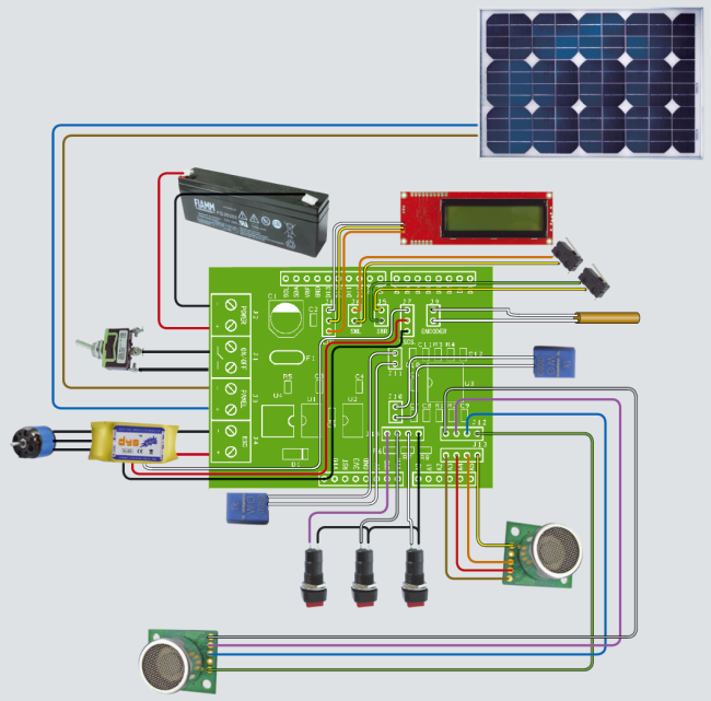
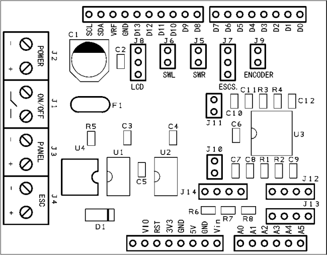
As for the electric connections of the shield, make reference to the following table:
Tab.2 – Links of the shield connectors
| connector | function |
| J1 | Ignition switch |
| J2 | Battery Power |
| J3 | Photovoltaic panel |
| J4 | Electronic speed control (ESC) for the cutting engine |
| J5 | Obstacle detection Switch left |
| J6 | Obstacle detection Switch right |
| J7 | Cotrol signal for the speed control of the cutting engine |
| J8 | LCD Display |
| J9 | Reed contact for the rear pivoting wheel |
| J10 | 1mH Reel for underground wiring detection left |
| J11 | 1mH Reel for underground wiring detection right |
| J12 | Ultrasonic Sensor SRF-02 right |
| J13 | Ultrasonic Sensor SRF-02 left |
| J14 | Buttons |
We shall list below all the hardware components used in this project:
N°2 micromotor gearboxes RH-158-12-200
N°2 wheel hub
N°2 Ultrasonic sensor SRF02.
N°1 lead battery 2,1Ah NP21-12
N°1 Solar Panel STP10M 10W 0,59A
N°1 LCD serial display for diagnostics 1446-LCDSER16X2NV
N°1 brushless motor for aeromodelling BMA20-22L
N°1 speed control for Brushless motors ESC-18A
N°1 magnetic sensor for alarm systems (used as encoder)
The energy balance allows us to understand the useful energy cycle and how much work can be done in a day:
- current absorbed by the cutting engine, about 1,4A
- current absorbed by the electronics 0,07A
- current absorbed by the engines 0,4A
- current absorbed by the photovoltaic panel, about 0,6A
From the measured data (with the said set-up) we may infer that the current needed for running the machine is three times the current supplied by the photovoltaic panel, that is to say that for an hour of work three hours of recharge are needed, with a useful employment percentage of 30%. Considering that in summer, in optimal conditions, about nine sunny hours are available, we may supposed to have about three hours for cutting in a day, which should normally be more than enough to keep in order a garden up to 500m2.

BOM
R1: 10 Mohm (0805)
R2: 100 kohm (0805)
R3: 10 Mohm (0805)
R4: 100 kohm (0805)
R5: 390 ohm (0805)
R6: 4,7 kohm (0805)
R7: 2,2 kohm (0805)
R8: 6,8 kohm (0805)
C1: 100 µF 25 VL (D)
C2: 100 nF (0805)
C3: 470 nF (0805)
C4: 470 nF (0805)
C5: 100 nF (0805)
C6: 100 nF (0805)
C7: 22 nF (0805)
C8: 1 nF (0805)
C9: 1 nF (0805)
C10: 22 nF (0805)
C11: 1 nF (0805)
C12: 1 nF (0805)
U1: ACS712ELCTR-05B-T
U2: ACS712ELCTR-05B-T
U3: CD4069UBM
U4: ASSR-1611-301E
F1: RUEF300
D1: GF1M
Firmware
/*
  SolarMower V1.0
  SolarMower use mowershield_FE
  2014 Mirco Segatello
  For hardware see www.elettronicain.it

  Press PEN during power-on for ESC test
  Press PUP during power-on for test motor
  Press PDW during power-on for test sensor
 */

#include <EEPROM.h>
#include <SoftwareSerial.h>
#include <Servo.h>
#include "Wire.h"
#include "SRF02.h"
#include "Configuration.h"

Servo ESC;

//variables
float VBat;               // Battery voltage [V]
int VBatPC;               // Battery voltage percentage
float VBatScale=0.054;    // Battery scale for Volt converter
float IPanel;             // Panel current [A]
float IPanelOffset;       // Panel current offset
float IPanelScale=0.185;  // Panel current scale V/A
float ICut;               // Motor cut current [A]
float ICutOffset;         // Motor cut current offset
float ICutScale=0.185;    // Motor cut current scale V/A
int i;
int cutPower=0;           // Cut Power from 0%=ESC_MIN_SIGNAL to 100%=ESC_MAX_SIGNAL
int cutPower_uSec=ESC_MIN_SIGNAL;      // Cut Power from ESC_MIN_SIGNAL to ESC_MAX_SIGNAL
int oldSpeed=0;           // Speed of mower (0-255)
float IPanelMax=0;           // IPanel max current
unsigned long BWFL_count;
unsigned long BWFR_count;
unsigned long previousMillis = 0;
unsigned long currentMillis;
volatile int mowerStatus=0; // 0=oncharge (press pen for run)
                            // 1=run
                            // 2=stuck
                            // 3=search
                            // 4=batlow
                            // 5=charge and restart when full
                            // 6=cuterror
volatile unsigned long wheelTime=0;

// LCD does not send data back to the Arduino, only define the txPin
SoftwareSerial LCD = SoftwareSerial(0, LCD_pin);
int LCD_Page = 0;         // Page to display

SRF02 US_SX(US_SX_address, SRF02_CENTIMETERS);
SRF02 US_DX(US_DX_address, SRF02_CENTIMETERS);


void setup()
{
  Serial.begin(9600);
  Wire.begin();
  pinMode(Encoder_Pin, INPUT_PULLUP);
  pinMode(PWMA_pin, OUTPUT);
  pinMode(DIRA_pin, OUTPUT);
  pinMode(BWFR_pin, INPUT);
  pinMode(BWFL_pin, INPUT);
  pinMode(Panel_pin, OUTPUT);
  pinMode(ESC_pin, OUTPUT);
  pinMode(SWOR_pin, INPUT_PULLUP);
  pinMode(SWOL_pin, INPUT_PULLUP);
  pinMode(PWMB_pin, OUTPUT);
  pinMode(DIRB_pin, OUTPUT);
  pinMode(LCD_pin, OUTPUT);

  digitalWrite(DIRA_pin, LOW);
  digitalWrite(DIRB_pin, LOW);
  analogWrite(PWMA_pin, 0);
  analogWrite(PWMB_pin, 0);
  digitalWrite(Panel_pin, LOW);


  // For SerialMonitor diagnostic
  Serial.println("Solar Mower V1.0\n");
  Serial.println("Init ESC...");
  ESC.attach(ESC_pin);
  cutOFF();

  Serial.println("Init SerLCD...");
  serLCDInit();
  clearLCD();
  lcdPosition(0,0);
  LCD.print("Solar Mower v1.0");
  lcdPosition(1,0);
  LCD.print("Init...");


  Serial.println("Init Sensor");
  sensorInit();
  Serial.print("IPanelOffset= ");
  Serial.println(IPanelOffset);
  Serial.print("ICutOffset= ");
  Serial.println(ICutOffset);
  Serial.println();


  // TEST MOTOR
  if (Button(Button_pin)==PUP)
  {
    while(1)
    {
      clearLCD();
      lcdPosition(0,0);
      LCD.print("Test motor");
      lcdPosition(1,0);
      LCD.print("PEN begin test  ");
      Serial.println("Press PEN for begin motor test");
      while (Button(Button_pin)!=3) { }
      testMotor();
    }
  }

  //TEST SENSOR
  if (Button(Button_pin)==PDW)
  {
      clearLCD();
      lcdPosition(0,0);
      LCD.print("Test sensor");
      Serial.println("Test sensor");
      delay(1000);
    while(1)
    {
      sensorReading();

      clearLCD();
      lcdPosition(0,0);
      LCD.print("VB=");
      LCD.print(VBat);

      lcdPosition(0,9);
      if ((US_DX.read()>0) && (US_DX.read()<USdistance))   {
            LCD.print("UsDX ");
            Serial.println("UsDX");
      }
      if ((US_SX.read()>0) && (US_SX.read()<USdistance)) {
            LCD.print("UsSX ");
            Serial.println("UsSX");
      }
      if ( (BWFL_count>3000) && (BWFL_count<4000) ) {
            LCD.print("BWFL");
            Serial.println("BWFL");
      }
      if ( (BWFR_count>2000) && (BWFR_count<4000) ) {
            LCD.print("BWFR");
            Serial.println("BWFR");
      }
      if (digitalRead(Encoder_Pin)==0) {
            LCD.print("Encoder");
            Serial.println("Encoder");
      }
      if (digitalRead(SWOR_pin)==0) {
            LCD.print("SWOR");
            Serial.println("SWOR");
      }
      if (digitalRead(SWOL_pin)==0) {
            LCD.print("SWOL");
            Serial.println("SWOL");
      }
      if (Button(Button_pin)==1) {
            LCD.print("PUP");
            Serial.println("PUP");
      }
      if (Button(Button_pin)==2) {
            LCD.print("PDW");
            Serial.println("PDW");
      }
      if (Button(Button_pin)==3) {
            LCD.print("PEN");
            Serial.println("PEN");
      }

      lcdPosition(1,0);
      LCD.print("IC=");
      LCD.print(ICut);
      Serial.print("IC=");
      Serial.println(ICut);
      lcdPosition(1,9);
      LCD.print("IP=");
      LCD.print(IPanel);
      Serial.print("IP=");
      Serial.println(IPanel);

      delay(250);
    }
  }

  //TEST ESC
  if (Button(Button_pin)==PEN)
  {
    Serial.println("Test ESC...");
    clearLCD();
    lcdPosition(0,0);
    LCD.print("Test ESC");
    while(1)
    {
        sensorReading();
        cutPower = map(cutPower_uSec, ESC_MIN_SIGNAL, ESC_MAX_SIGNAL, 0, 100);
        lcdPosition(0,9);
        LCD.print("IC=");
        LCD.print(ICut);
        lcdPosition(1,0);
        LCD.print("cutPower=");
        LCD.print(cutPower);
        LCD.print("%  ");
        Serial.print("cutPower=");
        Serial.print(cutPower);
        Serial.print("%   usec=");
        Serial.println(cutPower_uSec);

        if (Button(Button_pin)==2)
           if (cutPower_uSec<ESC_MAX_SIGNAL) cutPower_uSec += 20;
        if (Button(Button_pin)==1)
           if (cutPower_uSec>ESC_MIN_SIGNAL) cutPower_uSec -= 20;

        ESC.writeMicroseconds(cutPower_uSec);
        delay(200);
    }
  }
  attachInterrupt(0, rotate, FALLING);
}


void loop()
{
  //main program
  digitalWrite(Panel_pin, HIGH);

  main:
  //wait for PEN press
  while(Button(Button_pin)!=3)
  {
    currentMillis = millis();
    if(currentMillis - previousMillis > timeClock)
    {
        sensorReading();
        LCDdebug();
    }
  }

  Serial.println("GO!");
  mowerStatus=1;
  IPanelMax=0;
  LCDdebug();
  cutON();
  setMowerSpeed(255);


  //main loop
  while(1)
  {

    //ferma tutto
    if (Button(Button_pin)==PUP || Button(Button_pin)==PDW)
    {
      cutOFF();
      setMowerSpeed(0);
      mowerStatus=0;
      goto main;
    }

    //if not an interrupt wheels occurs within 10 seconds, the robot is blocked
    if (millis()>wheelTime+10000)
    {
      cutOFF();
      setMowerSpeed(0);
      mowerStatus=2;
      goto main;
    }

    // gestione sensori ostacolo
    if (digitalRead(SWOL_pin)==LOW) obstacleAvoidSX();
    if (digitalRead(SWOR_pin)==LOW) obstacleAvoidDX();


    // reads the sensors every timeClock
    currentMillis = millis();
    if(currentMillis - previousMillis > timeClock)
    {
      previousMillis = currentMillis;

      sensorReading();

      if ((US_DX.read()>0) && (US_DX.read()<USdistance))
      {
            obstacleAvoidSX();
            resetEncoder();
      }
      if ((US_SX.read()>0) && (US_SX.read()<USdistance))
      {
            obstacleAvoidDX();
            resetEncoder();
      }
      if ((BWFL_count>3000) && (BWFL_count<4000))
      {
            obstacleAvoidSX();
            resetEncoder();
      }
      if ((BWFR_count>2000) && (BWFR_count<4000))
      {
            obstacleAvoidDX();
            resetEncoder();
      }


      //**********************************************************************
      if (IPanel>IPanelMax) IPanelMax=IPanel; //memory to max current on panel

      //battery lower then 10% then searching the point to charge
      if (VBatPC<10)
      {
        mowerStatus=3;
        cutOFF();  //stop cut
      }

      //continues to advance until it finds a light source at least 80% of the previous maximum.
      if (mowerStatus==3)
      {
        if  (IPanel>IPanelMax*0.8)
        {
          setMowerSpeed(0);
          mowerStatus=5; //charge with restart
        }
      }
      //**********************************************************************

      if (mowerStatus==5)
      {
        resetEncoder();
        // full charge then restart
        if (VBatPC>=100)
        {
            mowerStatus=1;
            IPanelMax=0;
            cutON();
            setMowerSpeed(255);
        }
      }

      if (VBat > VBat_Level_Max)
      {
         //lead battery never stop charge
         //disable charge only for lipo battery
         //digitalWrite(Panel_pin, LOW);
      }

      //battery is completely discharged
      if (VBat < VBat_Level_Min)
      {
        cutOFF();
        setMowerSpeed(0);
        digitalWrite(Panel_pin, HIGH);
        mowerStatus=4;
        goto main;
      }

      // ICut too high
      if (ICut > ICut_Max)
      {
        cutOFF();
        setMowerSpeed(0);
        digitalWrite(Panel_pin, HIGH);
        mowerStatus=6;
        goto main;
      }

      serialDebug();
      LCDdebug();
      }
  }
}

void rotate()
{
  wheelTime=millis();
}

void resetEncoder()  //reset value for block wheels
{
  wheelTime=millis();
}

void obstacleAvoidSX()
{
      // obstacle avoid
      setMowerSpeed(-PWMSpeed);
      delay(timeReverse);
      setMowerRotate(-PWMSpeed); //gira a sinistra
      delay(timeRotate);
      setMowerSpeed(PWMSpeed);
}

void obstacleAvoidDX()
{
      // obstacle avoid
      setMowerSpeed(-PWMSpeed);
      delay(timeReverse);
      setMowerRotate(PWMSpeed);
      delay(timeRotate);
      setMowerSpeed(PWMSpeed);
}


void setMowerRotate(int newSpeed)
{
  //rotate mower (first set speed at zero)
  constrain(newSpeed, -255, 255);
    for (i=oldSpeed; i>=0; i--)
    {
       analogWrite(PWMA_pin, i);
       analogWrite(PWMB_pin, i);
       delay(accelerateTime);
    }
    oldSpeed=0;

  if (newSpeed<0)
  {
    digitalWrite(DIRA_pin, HIGH);
    digitalWrite(DIRB_pin, LOW);
    newSpeed=-newSpeed;
  }
  else
  {
    digitalWrite(DIRA_pin, LOW);
    digitalWrite(DIRB_pin, HIGH);
  }

  for (i=0; i<=newSpeed; i++)
  {
       analogWrite(PWMA_pin, i);
       analogWrite(PWMB_pin, i);
       delay(accelerateTime);
  }
  oldSpeed=newSpeed;
}


void setMowerSpeed(int newSpeed)
{
  //set new speed for mower (first set speed at zero)
  constrain(newSpeed, -255, 255);
    for (i=oldSpeed; i>=0; i--)
    {
       analogWrite(PWMA_pin, i);
       analogWrite(PWMB_pin, i);
       delay(accelerateTime);
    }
    oldSpeed=0;

  if (newSpeed<0)
  {
    digitalWrite(DIRA_pin, HIGH);
    digitalWrite(DIRB_pin, HIGH);
    newSpeed=-newSpeed;
  }
  else
  {
    digitalWrite(DIRA_pin, LOW);
    digitalWrite(DIRB_pin, LOW);
  }

  if (newSpeed > oldSpeed)
  {
    for (i=oldSpeed; i<=newSpeed; i++)
    {
       analogWrite(PWMA_pin, i);
       analogWrite(PWMB_pin, i);
       delay(accelerateTime);
    }
  }
  else
  {
    for (i=oldSpeed; i>=newSpeed; i--)
    {
       analogWrite(PWMA_pin, i);
       analogWrite(PWMB_pin, i);
       delay(accelerateTime);
    }
  }
  oldSpeed=newSpeed;
}


void cutON()
{
  //cutter ON
  for (cutPower_uSec=ESC_MIN_SIGNAL; cutPower_uSec<=ESC_MAX_SIGNAL; cutPower_uSec += 10)
  {
    ESC.writeMicroseconds(cutPower_uSec);
    delay(50);
  }
  wheelTime=millis();
}

void cutOFF()
{
  //cutter OFF
  ESC.writeMicroseconds(ESC_MIN_SIGNAL);
}
The sketch has been divided in different files, each one with a specific purpose, allowing to order the functions and make the reading easier; we shall see below the files composing the sketch.
The file configuration.h contains all the define instructions used to set up the working parameters and the assignation of all pins for Arduino. Among all the parameters, the most important ones are:
ESC_MAX_SIGNAL 2000: it defines the duration (in microseconds) of the signal relating to the maximum power of the ESC, as regards the control of the cutting engine.
#define ESC_MIN_SIGNAL 1000: it defines the duration (in microseconds) of the signal relating to the ESC stopping, as regards the control of the cutting engine.
#define VBat_Level_Min 9.0: it defines the minimum voltage of the battery: under this value all the lawn mower functions are deactivated, with the exception of the solar panel recharge.
#define VBat_Level_Max: it defines the maximum voltage of the battery: above this value the recharge from solar panel is interrupted. The mimimum and maximum value are also used to determine the battery charge level.
#define ICut_Min: it defines the minimum current absorbed by the cutting engine: below this value an alarm is generated.
#define ICut_Max: it defines the maximum current absorbed by the cutting engine: above this value the advancement speed is reduced.
#define accelerateTime: it defines the duration of the acceleration for the engines assigned to movement; the total acceleration time amounts to accelerateTime*255[msec].
#define Usdistance: the distance (in centimeters) within which an obstacle is detected and the robot changes direction.
#define timeReverse: duration (in milliseconds) of the reverse motion of the robot, following the detection of an obstacle.
#define timeRotate: duration (in milliseconds) of the rotation of the robot during the manoeuvre to modify the direction of travel, after having detected an obstacle.
The file SerLCD.ino contains the functions for the initialization and the control of the LCD display. The file debug.ino contains the functions for the initialization and the visualization on the LCD display of the values measured during the running of the robot, and also contains the functions used to send the measured data to the PC.
The file sensor.ino contains the functions used when reading the sensors; all of the measured values are converted in ampères and volts for easy comparison. Particularly interesting is the FreqCounter(int pin, unsigned long gateTime) function, that allows to measure the number of impulses coming from the inputs used for the detection of the underground wiring.
The square wave signal, obtained from the circuit for the detection of the underground wiring, presents a particular frequency only in the case the wire is correctly detected.
The parameter gateTime shows the duration of the detection of the signal and also represents the time needed by the function to count, whose default value amounts to 100msec. The file TestMotor.ino contains the function used during the test for the traction engines.
For each function of the lawn mower, a confirmation is given on the LCD display, and equivalent messages are sent to the PC: the LCD display grants a greater convenience for the data management, without the need of a PC connection.
The main program is contained in the file SolarMower.ino: it oversees all operations and deals in recalling all the functions in the correct sequence.
Once the electric part is complete, it is needed to correctly verify the functionalities and the wiring: for this purpose three specific utilities have been predisposed. We shall remember that the blades to cut the grass are very dangerous, therefore we recommend to remove the blades until you end all tests.
When igniting, or when pressing the reset button of Arduino, or when rebooting the Serial Monitor (if connected to Arduino) the firmware will start its elaboration; as a first operation it will verify if one of the buttons is pressed, being the case, it will start the specific set-up procedure, as follows:
PUP button pressed, to enter the sensors test;
PDW button pressed, to enter the engines test;
PEN button pressed, to enter the ESC test.
The procedure of the ESC test allows to calibrate the maximum and minimum values; it is not a programming sequence, which would need, on the contrary, to make reference to the specific manual of the ESC being used.
1 disconnect the cutting blade and the ESC power connector.
2 power the lawn mower and the ESC test entries.
3 set the cutPower to the maximum, by using the PUP 100%=2000usec button
4 power the ESC and wait for the configuration of the maximum point (you will hear a specific acoustic signal).
5 set the cutPower to the minimum, by using the PDW button (you will hear a specific acoustic signal).
6 The calibration will be complete now. The ESC will automatically set the limits in a 10-30% range for the minimum and a 70-100% range for the maximum. By operating on the PUP and PDW buttons it is possible to modify the value of cutPower and verify that the motor is correctly running.
To verify the movement engines, boot the engines testing procedure: it will start the two motors, in order, by gradually accelerating and decelerating them. You will have then to verify that the way of rotation is concurring with the messages visualized on the Serial Monitor of Arduino, or on the LDC display: should the way of rotation be differing, it is sufficient to reverse the engines’ wires. You will also have to verify that the DX engine is actually matching the right engine and vice versa.

Before booting the sensors testing procedure, we have to talk about the ultrasonic sensors: since they’re both connected to the same I2C BUS, it is needed that one of them is programmed with a different address. The sensors are of the SRF02 kind, and are sold with the value address HEX0x70 being assigned. Therefore, the two sensors that have just been bought would go in conflict if connected to the same BUS. We will leave the left sensor with the default address 0x70 and we will modify the address for the right sensor.
To do this, connect the shield to the right sensor alone, and open the SRF02_address.ino sample, that is contained within the SRF02 library and supplied along with the files of this article, then load it on Arduino; the address will be modified automatically. You may use the sample program, contained as well within the library, to verify that the change of address correctly happened.
By booting the sensors testing procedure, you will have the chance to verify if all input peripherals are running correctly; both on the LCS display (if available) and the Serial Monitor (if connected to Arduino) it will be possible to see the data that have been acquired from the current sensors, the value of the digital entries and the presence or not of detected obstacles.
Once sure that everything is working correctly, you may make the first field tests: it is sufficient to press the PEN button on the main screen to start the lawn mower, while it will stop immediately by pressing one of the two buttons, PUP and PDW.
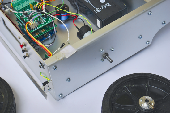
Anyway, before lifting up or handling the lawn mower, we advise to turn it off by means of the general switch: only this will grant you that no mechanism will start working.
Without entering the details of the whole firmware, let’s see now the essential lines that have been implemented in this first versoin; the idea is to implement a finite-state automaton whose operating status is memorized in the mowerStatus variable.
When the status variable takes the value 0, on the display the word CHARGE will be shown: this is the initial state soon after the ignition, and the robot is still and charging, waiting for the PEN boot button to be pressed.
When the status variable takes the value 1, on the display the word RUN will be shown: this is the major status, with the robot cutting the grass and at the same time verifying the presence of obstacles. In this case a simple procedure will start, that will modify the direction of travel.
When the status variable takes the value 2, on the display the word STUCK will be shown: in this state the robot got stuck. The situation is detected since the rear wheel stopped turning and doesn’t give any signal to the board.
When the status variable takes the value 3, on the display the word SEARCH will be shown: in this state the battery is close to low, the cutting engine is stopped and the robot looks for a luminous place to recharge itself.
When the status variable takes the value 4, on the display the word BATLOW will be shown: in this state the battery is low, and it was impossible to find a satisfactory recharging place. Even the traction motors are stopped and the robot remains in recharge mode.
When the status variable takes the value 5, on the display the word CHARGE RS will be shown: in this state the robot is in recharge position and will be ready to start again once the battery is completely recharged.
When the status variable takes the value 6, on the display the word CUTERROR will be shown: in this state the robot is still, since it detected an anomaly in the absorption of the current of the cutting engine.
The circuit to power the underground wiring

As previously mentioned, it is needed that the underground wiring forms a closed ring, and that it is powered by an alternating signal at the frequency of 34Khz. To do this, a very simple astable circuit is needed. It is created with a NE555 integrated circuit and a few more components; the circuit is the same of the previous version and calculates the connection to a transformer with a 9volt secondary, in turn connected to the electric network at 220Vac.

Consistently with the philosophy behind this project, it is however advisable that the power supply is autonomous from the electric network, by using a small solar panel and a buffer battery. The solar panel will be the main power supply to the circuit, while a 12V battery (connected in parallel to the C1 capacitor) will be the main power supply in case of insufficient exposure to the sun. The presence of a bridge rectifier will prevent the battery tension from entering the solar panel during the periods of low sun exposure. To correctly balance the system, it is needed to make sure that during the night the battery is capable of powering the circuit without getting too low, while the solar panel will have to be able to power the circuit and, at the same time, to recharge the battery during the day.


The system is not unlike the one used in the solar energy lamps in the garden, that do not need electric wiring to the home network. The underground wiring will be laid in a way to create a closed ring to mark the limits of the lawn mower working area. Any further obstacle within this area will be avoided thanks to the on-board sensors.
The only calibration to carry out concerns the frequency regulation of the signal sent to the underground wiring: it is sufficient to near the cable to the BWF sensors’ reels and to rotate the trimmer until the best possible reading is obtained (for this purpose, use the sensors testing procedure).
BOM
R1: 3,3 kohm
R2: 12 kohm
R3: 100 ohm
R4: 4,7 kohm MV
C1: 1.000 μF 35 VL
C2, C4: 100 nF
C3: 1,2 nF 63 VL
C5: 1 μF 63 VL
PT1: W06M
U1: NE555
Mechanical designs

In the store
The mower shield is available in our Store
The lawn mower presented in this post is only an example of how it could be create but, starting from the chassis and up to the electro-mechanic part, you can customize the different components to your liking, and find the best solution for your specific exigencies. Far from being a lawn mower that can substitute a commercial product (that has very different pricings), it can be useful to understand the real possibilities of this kind of robot.

Add link in the article to the magazine, or where to get(buy) the magazine plz.
A good improvement might be replacing the PV solar panel with miniaturised solar thermal. Solar thermal can achieve higher efficiencies.
ChE Capstone Project: Design of a Portable Solar Thermal Power Generator
http://arstechnica.com/science/2014/08/hydropower-no-longer-majority-of-renewable-energy-in-the-us/
http://www.ret-erau.com/Images/Labs/2012/solarStirling2.jpg
ops… sorry I add the mechanical parts
Thank you for the quick response.
Links to manufacturers datasheets for the components used and what manufacturer you used would be very appreciated. The project’s open source nature asks component data sheets.
[…] of braving the oven-like temperatures which will inevitably drench the person in sweat, this solar powered robot has been created ready to take on the job. With the heart of an Arduino, this device shaves down […]
I am really sorry for you that his nice device is using a shitduino. 100% useless.
This may have had so much potential.
It’s alright if you don’t like Arduino, but you shouldn’t use its name in a disparaging manner. Not very mature.
What is your point? The arduino is perfect for this application. Which board are you referring to?
Ps: I can’t believe you received 10 upvotes…
Obviously a lawn mower needs to be controlled with an NSA sized super computer?
[…] Si vous souhaitez avoir plus de détails pour fabriquer votre propre robot tondeuse, il va falloir que vous maîtrisiez bien le monde de l’électronique et des Arduinos. […]
[…] The equivalent of a Roomba for your lawn, this open-source robotic lawn mower runs entirely on solar power so you don’t have to sweat it out on a hot summer day. No need to even control it via remote, since it’s totally autonomous. If you’re handy with electronics, you can try making one yourself – instructions are available at Open Electronics. […]
[…] The equivalent of a Roomba for your lawn, this open-source robotic lawn mower runs entirely on solar power so you don’t have to sweat it out on a hot summer day. No need to even control it via remote, since it’s totally autonomous. If you’re handy with electronics, you can try making one yourself – instructions are available at Open Electronics. […]
[…] this tutorial is presented a solar-powered Arduino robot engineered to mow the grass and work in a defined garden […]
[…] A Robotic lawn mower powered by Solar Energy with an Arduino heartPosted 1 month ago […]
Thanks for this project.Have built an autonomous mower -no where near as good as this!.Am on waiting list for shield,as want to build.Is the magazine mentioned in article still available; if so what is title and where do you order ? I can not get the page large enough to read the mechanical side of things and don’t mind buying book to give something back. Once again a big thankyou from New Zealand.
Hi, you can click on the images to see them bigger
[…] A Robotic lawn mower powered by Solar Energy with an Arduino heart. This robot will mow the grass of your garden, staying within a defined area, avoiding all obstacles and working in complete autonomy, automatically charging itself with a solar panel. […]
I’m very eager to build this robot but I’ve been over this post several times and find it lacking on key information. A full listing of all parts is needed. Where is the information on the blade? A better diagram on the chasis and construction material? Please post more information or a link to a more complete discussion and construction instructions.
Excellent concept, design and construction. I can’t wait to build it.
Thanks
Michael
see the tag. There are other posts
You have not given most of the essential things i want the component list I mean all the components expect form above component list and please in which software you executed the program
When veryfy firmware get error
SolarMower.cpp.o: In function `sensorReading()’:
/Arduino/Sensor.ino:38: undefined reference to `SRF02::update()’
SolarMower.cpp.o: In function `__static_initialization_and_destruction_0′:
/Arduino/SolarMower.ino:53: undefined reference to `SRF02::SRF02(unsigned char, unsigned char)’
/Arduino/SolarMower.ino:54: undefined reference to `SRF02::SRF02(unsigned char, unsigned char)’
collect2: error: ld returned 1 exit status
Fel vid kompilering.
???
have you installed the library?
I have a mechanical question! Does it works with long grass? Because I cannot see the robot cutting the grass in the video.
Thank you!
The robot need to cut continuosly the grass. If you cut long grass you have to remove it
How did you do the cut
ting plate?
We use a CNC machine
[…] We used float type variables only when it was strictly necessary and we implemented a system interrupt to manage, with the right timing, the stabilization operations. We did not skimp on protection systems and diagnostic messaging because, as an open source project, it must be easy to manage. Despite the hardware has already been described in previous articles, a small but crucial detail remained suspended: the scale of the gyro. In the first tests we used the gyroscope with a scale of 30 °/sec – definitely the optimum value when Openwheels is moving – which, however, in some situations led to a reading overflow. LCD Settings The management of all user customizable parameters is made through the LCD display, which also performs the function of monitoring the main diagnostic values. LCD Encoding errors current sensor. Adjusting the PID Parameters in the firmware. A Robotic lawn mower powered by Solar Energy with an Arduino heart. […]
Hi all,
Im trying to build this but where is the configuration.h file?
https://www.google.be/url?sa=t&rct=j&q=&esrc=s&source=video&cd=1&cad=rja&uact=8&ved=0ahUKEwjr4qagpbHMAhVG2ywKHQXTDTcQtwIIHjAA&url=https%3A%2F%2Fwww.youtube.com%2Fwatch%3Fv%3DnP5QrqGpaxg&usg=AFQjCNFDp1RZsNzT30pJppGKou9UCjGSCA&bvm=bv.120853415,d.bGg
end of summer 2015 with the weak motors like in this project. changed them. My garden is not level so… Link of code and information in the comments on youtube
I’m very new to Arduino but am considering this project – I have many questions but the first two that come to mind are:
1. What is the third shield board on the Arduino? I know that one is the Arduino board, the other is the mowershield board, but I don’t see any reference to explain the board in the middle.
2. Am I able to purchase the PCB for the ground wire signal generator?
Many thanks in advance!
@boris, i would like to know if u have design this and see it work, really appreciated the article above though, but cant get enough to design it. i would appreciate it if u can give full details on each components used and the circuit design. how do i get the components?
where is the wire.h file?
Can I control the lawn mower using LabVIEW software. I need mechanical specifications to do the Project.
Here http://www.open-electronics.org/wp-content/uploads/2014/08/Mechanical.png
Grande Boris! Che lavorone!
Non mi è chiara la parte del taglio dell’erba, ma il resto sembra chiarissimo!
Grazie ancora, mi sarà di grande ispirazione.
Any other people successfully build this mower? I’m at final build and am trying to troubleshoot. These instructions are too cryptic and difficult to understand. If you’ve had success getting the mower to run, email me if you think you can help.
Mrichardson at gmail dot com
Thanks!
correction
mrichardson364 at gmail dot com
What’s your problem?
Hello…this is a great project. There are many items I can change and fit to suit my needs. Thank you again for making this project.
Hi. Now 1 year into THE Build. Atlered your code but left your credentials in it. Added Bluetooth with commands and now Also when battery becomes low, advance to THE wire fence and follow wire untill charge current >1,5A. When charging stat there for 1h, reverse and continue. Needed to add at least one more coil in order to see where it is going on THE wire. After al is working is time to redessign THE looks of it! Now iTS a Frankenstein mashiene
Hi, great project!
What chassis did you use? was it DIY or you purchased it from somewhere?
Keep up your good work!
it’s a DIY chassis
i have a problem with configuration.h any idea??
Arduino:1.6.8 (Mac OS X), Tarjeta:”Arduino/Genuino Uno”
Opciones de compilación cambiadas, reconstruyendo todo
/var/folders/pg/r9jvxq217kd0p9l417lfr7br0000gn/T/arduino_modified_sketch_674093/sketch_may31a.ino:17:27: fatal error: Configuration.h: No such file or directory
#include “Configuration.h”
Download the complete sketch
Hello.
Love this project?
What kind of BWF- sensor is used? What about the knife arrangement?
Is it possible to use Nema steppermotors as drive motors?
Is it possible to use Nema stepmotors as drive motors.
Where do I find the library with confoguration.h ?
Get error in compieling the scetch.
hey i want to build this project. can you help me with your experience.?
Hello.
I am trying another question?
In description it show lcd-panel with 3 wires. My panel with I2C have 4 wires (gnd,vcc,sda,scl). How to connect?
And in description you describe a link soldered on A5 to a point on board. My board (pka03′) from welleman ordered from store, is different. Is this link needed on my motorshield?
Hello,
Had you an answer concerning the connecting of the screen with 4 sons(threads)?
Cordially
No I dont find any answer about 4 threads panel i2c.
I am not shure if there might be a “define lcd type i2c” or somthing like that in configuration.h to be activated. I will check this later?
I forgot…
I also have the same question concerning the link on the border A5.
An answer?
Thank you in advance
No sorry, no answer in 3 months.
My lawn mower project is on ice as I get stuck when panel not work.
Hoped there was anybody to tell wich panel or connections to be used, but nothing yet.
Thank you for having answered me … I am looking on the Internet.
In fact, we do not use the good screen … A screen of this type would be needed: http://www.futurashop.it/display-lcd-seriale-16×2-retroill.-neroverde-1446-lcdser16x2nv
I am in search of a possible adapter i2c towards ttl (I do not know if it exists …
Good evening
Yes it seems like that panel might work?
About adapter. What about this adapter from same shop?
http://www.futurashop.it/image/cache/catalog/data/data/controllo-seriale-per-display-lcd-600×600.jpg
Price is heavy and it is not far to buy finished panel.
Or maybe this?
https://www.ebay.com/itm/371001983836
I am not good on this but on net i found this:
TTL (Transistor Transistor Logic) is not a protocol. It’s an older technology for digital logic, but the name is often used to refer to the 5 V supply voltage, often incorrectly referring to what should be called UART.
Good evening
Good evening,
I moved forward little concerning the problem:
In
fact, I connected the screen directly on the arduino (GND, 5V, SDA and
SCL). I installed(settled) the LiquidCrystal_I2C bookshop and modified
little code. The problem which I have for the moment, it is that the
screen posts(shows) a little bit anything. I look, but were
hopeless(nil,worthless) in programming, I have a hard time…
Well after some search, I found this adapter:
https://www.sparkfun.com/products/258
I orderef one for 20 dollar with shipping?
This one will fit all my lcd’s ? and I will try it when received.
I guess it is the RX input that is needed for hour use?
God night?
Hello,
At the moment, I do not too much have time to take care of it…
Can you please be anxious me to inform about the functioning, or not, about the adapter of sparkfun?
The good end of day
I understand???? It is not my high priority now as the winter is comming here????
I will try it out when item received, and reply you then????
Great thank you.
Concerning me, I am in the course of manufacturing of the box(cash register) in addition to everything else…
We keep posted.
Good night
Hello
Tested today my new lcd adapter from Sparkfun.
It works?
Now I have to test the rest of my electronics?
I guess I have a way to go with the rest, but I will try when I get time later?
Hi there, I’m having issues with the tank circuit used as the receiver
for the fence. I suspect is the inductor i’m useing. What type of
inductor did you use?
Did you get any answer of this question? I have same problem.
i have one problem, lcd writes 232 Press CR_
I’m reading all the text but i don’t find anything about it
any solution ???
[…] Arduino Robotics – John-David Warren, Josh Adams, Harald Molle. Hubert's robots page. Arduino Robot 2 – Wandering Tank. Robot Store. How It Works: Husqvarna AutoMower 305. DIY Robot Lawn Mower. GARDENA Mähroboter R40Li – Installation (Teil 6: Begrenzungs- und Leitkabel) Wire guidance sensor. Fully Autonomous Golf Caddy. A Robotic lawn mower powered by Solar Energy with an Arduino heart. […]
Great project. Good luck in the future.
How to install configuration.h library?? and from where to download this library?
we will reply u soon
Hi!
Great project!
Please recommend different motor
micromotor gearboxes RH-158-12-200
something from this page:
http://www.dx.com/cs/s/dc%2bmotor?PageIndex=1#sortBar
thanks :)
What are the wheels?
Is not the 33rpm engine low?
https://www.robotstore.it/product/220/Motoriduttore-12V-33rpm-100Ncm-diam.40mm-RH158.12.200.html
Hello,
Can you direct me to the store links what PCBs i must buy ? I want to start this project. Please give me a hand.
Hey I have same situation. I want to work on this project. any suggestions ?? did you started on this ?
Hi, in our store you can find the shield https://store.open-electronics.org/index.php?_route_=MOWERSHIELD_FE
and in Related Products there are the others devices
Thank you sir. I will definately order this. I want algorithm and flowchart of this project. can you help me with that.
[…] kumanda gibi ilave özelliklere sahip servo motorları kullanarak zorlu arazilere erişebilir. Arduino, Robotik Çim Biçme Gücü’nü Güneş Enerjisiyle Çalıştırır : Bu robot bahçedeki çimlerin belirli bir alanda, tüm engellerden kaçınılarak biçilmesi için […]
Hello sir,
I want to work on this project. Can u give me a hand ?
Hello I can not change the address of SRF02
when I use SRF02_address the address is well change (flashing LED SRF)
but when I flash the arduino with solarmower.ino the 2 address get back on the same
I am a student from the Center for Advanced Technical Studies and i am working on a project that can use some of the similar ideas, is there anyway I can contact you seperately to ask questions?
What sensor did you use to detect the wire frequency?
The Mower shield has a input to detect the field
Thanks. One last question, what is this resistor? “4,7 kohm MV”. I cant seem to find it. Can you send a picture or key word to search for.
The trimmer. Vertical Mount
Still can’t find it. Is it a rheostat resistor? Do you have a kit maybe of your underground wire? Would much appreciate it. Thanks
Bro can you send me the component list and on which software you executed the program
Buon giorno, ho realizzato il progetto del rasaerba robot. costruito tutta la meccanica e assemblato l’elettronica.
ho scaricato il firmware e installato nell’arduino uno. ho il problema che il mower si accende ma il lcd non mostra nulla e il robot è fermo. il test dei motori e sensori con il monitor seriale funziona, il test dell’esc no. Ho controllato tutti i pin con il configuration.h e sono a posto. Bisogna apportare delle modifiche nel firmware? Grazie
SADF
Can I use the mower without induction wire? (with the ultrasonic sensor and with the 2i button) Can I use a Lithium 12V battery? Thanks for the answer
Can I use the mower without induction wire? (with the ultrasonic sensor and with the 2i button) Can I use a Lithium 11.1V battery? Thanks for the answer
[…] Arduino Operated Robotic Lawnmower Power by Solar Energy: This robot is designed to mow the grass in the garden within a defined area by avoiding all the obstacles. The entire circuit is powered with solar energy with Arduino controller as central control element. […]
Do you sell component kits for this? Or updates?
Lenovo’s shopping discounts can vary in terms of the amount and type of savings offered. Some discounts may offer a percentage off the total price of your purchase, while others may provide a flat discount or bundle deal.
To take advantage of Lenovo’s shopping discounts, you may need to use a coupon code or promotional offer at checkout. These codes can often be found on the Lenovo website, through email newsletters, or through third-party coupon sites.
Quel est le rôle de la deuxième plaque électronique. Aussi, vous n’avez pas précisé le branchement des 2 moteurs (gauche et droite) qui assurent la fonctionnalité du robot mobile
Solar and Arduino mean green lawn care tech that’s just plain cool. How does it perform under partial shade or cloud cover?
Impressive! Thanks for sharing this.