- Building a 3D Digital Clock with ArduinoPosted 3 months ago
- Creating a controller for Minecraft with realistic body movements using ArduinoPosted 4 months ago
- Snowflake with ArduinoPosted 4 months ago
- Holographic Christmas TreePosted 5 months ago
- Segstick: Build Your Own Self-Balancing Vehicle in Just 2 Days with ArduinoPosted 5 months ago
- ZSWatch: An Open-Source Smartwatch Project Based on the Zephyr Operating SystemPosted 6 months ago
- What is IoT and which devices to usePosted 6 months ago
- Maker Faire Rome Unveils Thrilling “Padel Smash Future” Pavilion for Sports EnthusiastsPosted 7 months ago
- Make your curtains smartPosted 7 months ago
- Configuring an ESP8266 for Battery PowerPosted 7 months ago
Save your Skin with this Open Source UV Index Detector
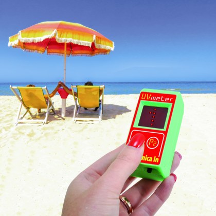
It measures solar radiation and visualizes the corresponding value on the integrated display of a miniaturized Arduino, in order to tell us when to expose ourselves to the sun…
Summer is just around the corner and whether you choose the seaside or the mountains for your holidays, there is no doubt that most of the people look for a sunny summer in order to come back with the most enviable suntan. Since sunlight contains ultraviolet rays, which are by the way responsible for our suntan, the first concern when it comes to sun rays is to protect ourselves, at least during the first days, with a sun lotion of adequate protection and by taking care to remain outside as little as possible, unless we have a sunshade or a sun umbrella. It is also useful to know the UV quantity contained in the sunlight, in fact, according to our geographic location and weather conditions, the atmosphere can retain UV rays more or less effectively. Getting to know the concentration (index) of UV rays is important because UV rays do not only cause sunburns but are also responsible for skin tumors, that is why we should try to get only the good part from the sun, which is composed of visible light or infrared light, and keep ultraviolet rays as far away as possible. This is the same reason why it is not recommended to sunbathe too long in certain geographical areas and on certain days. On an international level, UVI or UV index is the recognized parameter used to classify UV rays intensity, which is better described in the box you will find in these pages; that’s why in this article we are going to show you how to realize a device to measure and display the UV index, that you might use in order to verify the quantity of ultraviolet rays you are exposed to during your sunbathing session or, if you stay in the city, this will tell you when not to go out during the hottest afternoons in July and August and when you can go out with peace of mind, especially if you suffer from skin problems.
The circuit
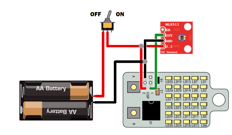
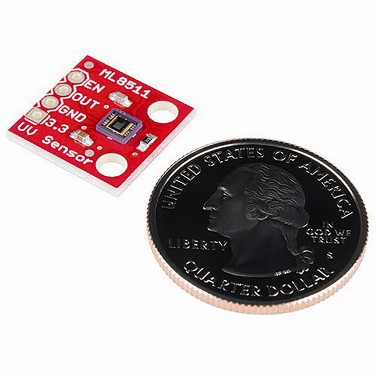
Upon deciding to go on with this project we asked ourselves a few things, such as what hardware to use and especially how to detect the intensity of ultraviolet rays, how to elaborate it and what solution should we employ to visualize it. We had no doubts about the sensor since we decided from the start to take advantage of an easily available, conveniently priced product that can be connected to any hardware. Specifically, we are going to use the ML8511 sensor in this project, that is directly mounted on the 6168-UVSENSOR breakout board.
The sensor is sensible to UV-A and UV-B radiation and can provide a voltage output ranging from 0,9 V to 2,9 V (provided it is powered by a voltage not lower than maximum desired output voltage). The ML8511 sensor can detect UV light with a wavelength ranging from 218 nm to 390 nm. As for the output, the sensor provides an analog voltage which is linearly proportional to the UV intensity expressly measured in mW/cm².
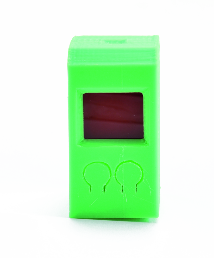
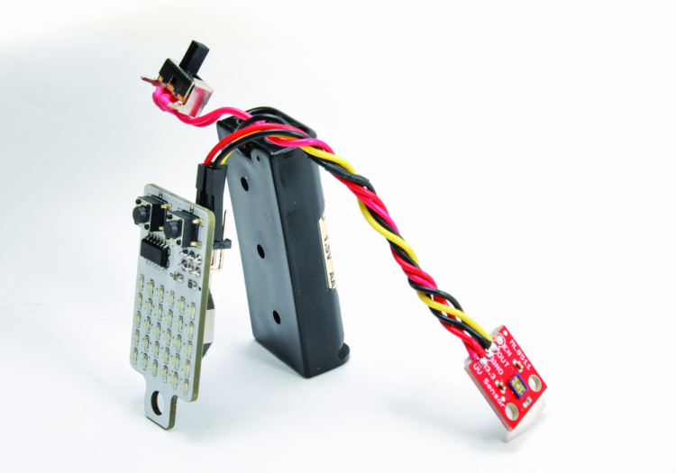
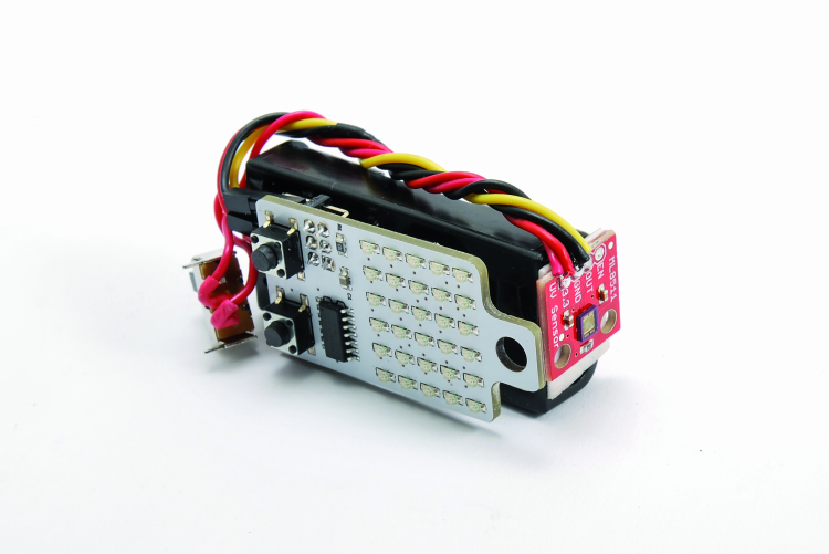
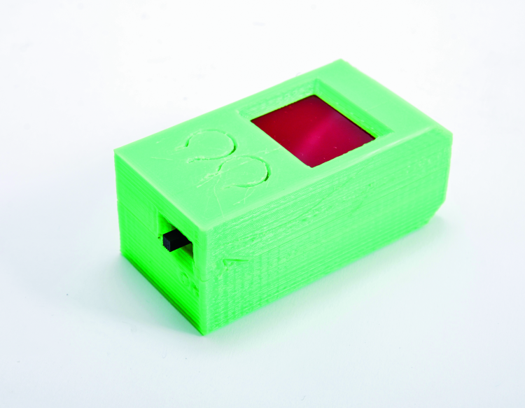
In our case, we decided to display the corresponding value through a very particular displaying element that is integrated on the same board containing the microcontroller and manages both image processing and composition; it’s an Arduino-based hardware, but it’s not on one of those standard boards, because we opted for a peculiar version equipped with a matrix display, called KeyChainino, already published in this post and documented on the website. This board is a minimal version of Arduino based on an Atmel microcontroller from the ATTiny series and it’s equipped with 3 V power, more than enough for our purposes, moreover, it has a LED matrix that is used in order to display the UV index. The 3 V power allows us to connect the board to the same power line of the UV sensor.
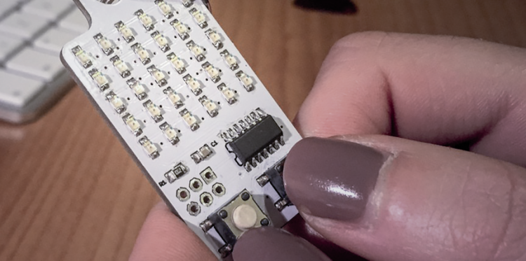
KeyChainino is a “display” which is entirely realized with a LED matrix controlled by a small microcontroller integrated into a printed circuit as big as a keychain. KeyChainino is composed of a 6 x 5 LED matrix and two buttons, everything is controlled by tiny ATTiny84A, an 8-bit Atmel microcontroller in SMD execution, which has just 14 pins, therefore it is small enough to allow us to place the whole circuit in a small plastic container. Since the Atmel microcontroller has a few pins in order to pilot the matrix LEDs, it employs a particular piloting technique called Charlieplexing, which is a sort of multiplex characterized by the fact that each LED of the matrix works only whenever the voltage at its terminals is such to polarize it directly. Thanks to a suitable connection and by positioning the LEDs as you can see in the circuit diagram, and by taking advantage of the fact that the pins of our microcontroller can enter three logic levels (HIGH, /LOW, Three-state), we can pilot more than one LED with one I/O.
The three-state level is obtained by setting a pin to make it work as digital input, it then enters in high impedance therefore strongly limiting the current passage (it basically behaves as an open circuit).
KeyChainino employs a 3 V CR2032 cell battery as power source, which is mounted on the board; unfortunately, our tests showed that this battery cannot provide the system (including the sensor) with an adequate level of power for longer periods of time, therefore we opted for two AAA batteries connected in series, in order to obtain 3 V. To provide a longer autonomy, we have added a switch connected in series to the power source, allowing us to power the device only when needed; this lets us to sensibly reduce power consumption and therefore extend the autonomy; as a matter of fact the system, even in standby, absorbs around 450 µA (in standby conditions, that is with the electronics part powered up and the LED matrix off).
Everything is interconnected as shown in the diagram you can see in these pages, you will also notice that the sensor output is connected to one of the contacts reserved to the ICSP connector with which we initially load the firmware into the microcontroller; three lines available on that connector, once the sketch is loaded, are available as I/O: they are MISO (1-pin of connector and 8-pin of ATTyny), MOSI (4-pin of connector and 7-pin of microcontroller) and SCK (3-pin of connector and 9-pin of microcontroller).
On the KeyChainino’s board, we’re also going to install a dedicated sketch that allows us to read the voltage provided by the UV sensor coming on the PB4 line mentioned above, which is initialized as analog input and then assigned to the A/D converter of the ATTiny.
Functioning
After powering the system, the sketch initializes the I/O lines and then goes on standby, waiting for an event to occur, which corresponds to pushing one of the KeyChainino’s buttons; until then, voltage on PB4 is ignored.
In order to start the reading and visualization process of the UV index, we just have to push either button, then the microcontroller starts reading voltage on PB4, provided by the sensor, and since the sketch contains a conversion table from voltage to UV index, the dedicated visualization routine pilots the LED matrix in Charlieplexing in order to show the corresponding scrolling value (only the integer part, without any decimals).
Once the key is released, after UV index is fully visualized, the LEDs will turn off.
If you want, as long as you keep the key pressed down, you can continually visualize the UV index measure, which will be updated and displayed only after calculating a mean value from a series of acquired values.
The sketch
In order to simplify the firmware’s compiling we decided to start from the “KeyChainino_basic” provided along with KeyChainino, which is the project’s original one; it contains the reading of the keys and the LED matrix handling in Charlieplexing, so it makes our work much easier. The firmware has been modified by adding the part that allows us to read an analog signal through the I/O foot and the A/D converter. To this purpose, we have left some comments for the instructions for the activation of the ADC converter, in order to take advantage of it in our case. Instructions with comments can be found in the setup() function and you can find them below:
<em>ADCSRA &= ~bit(ADEN); //disable ADC</em> <em>power_adc_disable(); // disable ADC converter</em>
Moreover, the loop() function has been modified in order to allow sensor reading when either one of the buttons on the KeyChainino expressed. In List 1 you can see such modified loop() function.
Listing1
void loop() {
if ((digitalRead(BUTTON_B)==LOW) || (digitalRead(BUTTON_A)==LOW))
{
digitalWrite(UV_EN,HIGH);
showAnalog(LetturaSensore());
}
else
{
digitalWrite(UV_EN,LOW);
goSleep();
}
}
For what concerns, on the other hand, the reading of the sensor’s value, we have used three interconnected functions. The first one is LetturaSensore() and it allows reading from analog port A5 of Arduino (this corresponds to pin PB4, which is ADC5 input of A/D converter in the Arduino mapping) from which a mean value will be calculated starting from a set number of read values defined by the “num_letture” variable, then the UV index will be shown (List 2).
Listing2
// Reading the analog value of the sensor
int LetturaSensore()
{
int uvVal = mediaAnalogRead();
float uvVolt = 3.0 * uvVal/1024;
float uvGrado = mappaValori(uvVolt, 0.99, 2.9, 0.0, 15.0);
uvInt=uvGrado;
return uvInt;
}
The second function employed is called mediaAnalogRead() and it allows to cyclically read the voltage value on port A5 and to calculate the average of various readings, in order to have a stable reference value that will be then used as a term of comparison (List 3).
Listing3
// Average after a certain number of readings established
// from the variable "num_letture"
// The resulting value is sent out of the function
int mediaAnalogRead()
{
unsigned int Valori = 0;
for(int x = 0 ; x < num_letture ; x++) // The average is done
Among the values read to have a true value
{
Valori += analogRead(A5);
}
Valori /= num_letture;
return(Valori); // Calculated mean value
}
The last function we used is called mappaValori() and it allows us to obtain the UV index (sensor surface radiation) related to the value read; the function, which can be found in List 4, makes use of the conversion table pertaining to the output voltage of sensor for the UV index which is memorized in the microcontroller and it employs a floating variable.
Listing4
// Based on the average value and range of sensor values, it is calculated
The UV Index
// The UV index is returned as a FLOAT output function
float mappaValori(float val, float v_min, float v_max, float uv_min, float uv_max)
{
return (val - v_min) * (uv_max - uv_min) / (v_max - v_min) + uv_min;
}
From openstore
KeyChainino – programmable keychain

Related Posts


One Comment
Leave a Reply
-
 Arduino ISP (In System Programming) and stand-alone circuits
We use an Arduino to program other ATmega without...
- Posted 12 years ago
-

-

-
 GSM GPS shield for Arduino
Shield for Arduino designed and based on the module...
- Posted 12 years ago
-
 Small Breakout for SIM900 GSM Module
Some post ago we presented a PCB to mount...
- Posted 13 years ago
-
 Building a 3D Digital Clock with Arduino
Project to create a digital clock consisting...
- Posted 3 months ago
-
 Acoustic amplifier – in DIY Kit
This kit creates a microphone amplifier with an output...
- Posted 4 months ago
-
 Creating a controller for Minecraft with realistic body movements using Arduino
Project of a controller that maps body movements...
- Posted 4 months ago
-

-
 Holographic Christmas Tree
Beautiful project to create a Persistence of Vision...
- Posted 5 months ago
Pingback: Open Source UV Index Detector - Electronics-Lab