- Building a 3D Digital Clock with ArduinoPosted 3 months ago
- Creating a controller for Minecraft with realistic body movements using ArduinoPosted 4 months ago
- Snowflake with ArduinoPosted 4 months ago
- Holographic Christmas TreePosted 5 months ago
- Segstick: Build Your Own Self-Balancing Vehicle in Just 2 Days with ArduinoPosted 5 months ago
- ZSWatch: An Open-Source Smartwatch Project Based on the Zephyr Operating SystemPosted 6 months ago
- What is IoT and which devices to usePosted 6 months ago
- Maker Faire Rome Unveils Thrilling “Padel Smash Future” Pavilion for Sports EnthusiastsPosted 7 months ago
- Make your curtains smartPosted 7 months ago
- Configuring an ESP8266 for Battery PowerPosted 7 months ago
Discovering the Open Source Ethernet Broadcaster
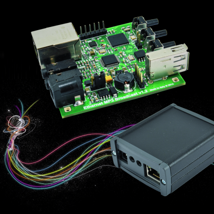
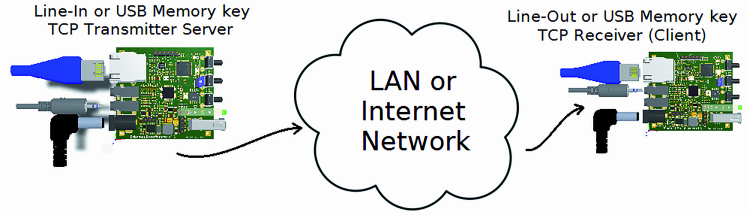
The idea we propose in this article is dedicated to all those who need to set up a sound/speaker system in a residential or industrial environment: could be a natural park, a church, a mall or any place where you have to spread a spoken/musical message. The module that we propose, called Ethernet Broadcaster, lets you sample an analog audio signal and transmit an audio stream to any room in your home or office using an Ethernet LAN as communication infrastructure, with the advantage of being easily extended with wireless devices.
Given the very broad requirements range, that may range from a home environment or a shopping center, we tried to make the software extremely flexible, allowing easy customization through dedicated web pages, to make it adaptable to many usage scenarios.
In fact, the module can be used not only to achieve point-to-point connection between two devices, but it is possible to setup broadcast communications from one to N devices. Moreover, the adoption of standard streaming audio protocols as SHOUTcast and IceCast makes the device compatible with web radios and PC media players (i.e. VLC media player). Combining these economic modules each other and a computer with a media player you can cover a wide variety of use cases thus allowing transmitting your radio inside a building, or outdoor, or notifying real-time warning messages.
The audio formats supported could be the world’s famous MP3 or its direct competitor (royalty free) Ogg Vorbis, making the whole system flexible and compatible with every private or business needs (and licensing issues!).

The circuit is equipped with some standard external connectors like the USB or Ethernet, and with some internal connectors reserved for special purposes. Given the different interaction modes considered for the design, it seems right to pay attention and explain how the circuit can be used and what role each of these connectors plays.
First, we have the power connector that looks like a 2.1 mm coaxial (positive on the center and negative on the external). Through this connector we can power the entire electronic circuit with a 5-15V DC voltage / 200mA current minimum (the USB device can vary the nominal value).
Using the J3 internal jumper you can select the input voltage: when the jumper is positioned on the right as in Fig.B, the onboard power stage will generate the 5V necessary to power both the board and the connected USB device, so the input voltage can be between 7V and 15V. If the jumper is moved to the left side as shown in Fig.A you have to power directly the system with a 5V source.

Beside the power connector, we find the audio input and output 3.5mm stereo jacks. The two connectors are compatible with consumer audio signals at -10 dBV (nominal level 316 mV rms) often labeled as Line-In and Line-Out (e.g. those found commonly on hi-fi systems).
Finally on the same side there is the RJ45 LAN connector. The device can operate at 10/100 Mbps favoring the latter in case of availability. It is also compatible with Gigabit (1000 Mbps) networks.
The two LEDs on the connector indicate the presence of a “link established and functioning correctly“ (green LED) and “regular IP traffic” (orange LED).
Moving to the opposite side, we find the USB Host useful to connect a USB pen-drive (Mass Storage Device). Almost all of the pen-drive or microSD USB adapters can be used without problems; the main limitation derives from the filesystem the mass memory is formatted to. Our software supports only FAT16 or FAT32 filesystems and is compatible with the “long file names”, so do not focus on the storage capacity but be sure to format the mass memory to the right filesystem.
On the same board side, you can find three buttons and four LEDs. For ease of discussion, we will name the three buttons as left, center and right. Similarly for the LEDs: the upper one is the red, the central one is the blue or central-red while the lower one is the green. During normal operation, the blue LED flashes at about 1Hz: since it is managed via software without using dedicated hardware interrupt, its absence or irregular flashing could indicate a board malfunctioning .
The other LEDs have different meanings depending on the context and are explained in the following paragraphs.
Exploring the board layout we see the J7 4-pin connector, described in Table. This connector can extend the software functionalities by communicating via I²C, UART or bit banging protocols with an external device.
Finally, J1 connector is the main microcontroller programming interface, this is generally used only at manufacturing to install the bootloader to the reserved flash memory area. Firmware updates can be made through special web pages, as explained later.
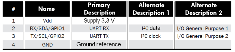
Description of J7 connector (2.54 mm pitch)
Electric scheme
The audio over Ethernet transmitter / receiver is equipped with a very powerful microcontroller named U2 in the circuit diagram. In particular, it has been chosen the Microchip Technology Inc PIC32MX695F512H, top of the 32MX family since it comes with 512 Kbytes of program memory and 128 Kbytes of RAM and it has all the necessary hardware to interface with a USB 2.0 peripheral and an Ethernet PHY to manage a 10/100 Mbps connection.
The 32-bit MIPS M4K® Core CPU, supporting cache and branch prediction can perform up to 105 DMIPS at only 80 MHz clock, making it particularly suitable for our purpose to manage multiple audio streams over an Ethernet network.
The operating temperature can be between -40 to 105 ° C and it requires only a stabilized 3.3 V power supply to work.
The microcontroller is equipped with standard peripherals: the Serial Peripheral Interface (SPI) used to communicate with the U7 chip, the Inter Integrated Circuit (I²C) to communicate with the outside through the J7 connector and the Universal Asynchronous Receiver-Transmitter (UART), also used to communicate with U7 or to external environment through J7.
Continuing the printed circuit analysis, the second very important component is U7 (VS1063): this is a MP3 slave processor manufactured by VLSI Solution. It is a component already used in other projects previously presented in this magazine. Its worth derives from its ability to play or record audio streams encoded in different formats including the famous Moving Picture Experts Group-1/2 Audio Layer 3 (MP3) and its royalty free close competitor Ogg Vorbis.
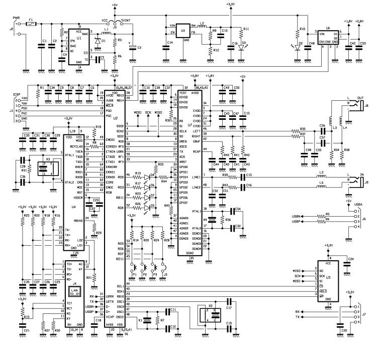
The two main components, U2 and U7, dialogue by means of an SPI channel shared with U5. Specifically we are using the SPI device number 2 and four additional digital lines: xCS, XDCS, RESET and DREQ. The first three lines are U7 input signals and correspond respectively to the U7 control section chip select (SPI mode), to the data section chip select and to a reset pulse for synchronizing the decoder and the microcontroller at boot. Finally the last signal, labeled with the abbreviation DREQ corresponds to a VS1063 output and indicates the availability of free space in its FIFO memory to the external microcontroller, to receive new commands and new data.
When working in default SPI mode with VS1063, it becomes very difficult to use the Direct Memory Access (DMA) feature on the microcontroller. To optimize the use of PIC available resources, VS1063 is connected to U2 also through a dedicated UART device that makes the use of DMA (especially during the registration process) much easier. In fact, you can set the use of a special buffer and its saturation generates an interrupt that alerts the main loop (“buffer full”), without needing a polling procedure for each byte generated by the decoder.
The SST25VF016B flash memory, labeled U5, is connected to the same SPI bus. This CMOS Flash memory has 16Mbit/2Mbyte capacity, so it can host all the application web pages and the jQuery libraries used for the dynamic page generation. The U5 chip is controlled also by a further two electrical signals generated by U2, WP and HOLD, which temporarily block or inhibit new content writing.
Regarding the power section, the circuit is equipped with two Low-dropout regulators (LDO) on a unique socket (SOT236), named U6 in the circuit diagram. The latter, in abbreviation AP7312-1828 is a cheap controller that provides two extremely accurate stabilized output voltages, respectively 1.8 V and 2.8 V with a maximum current of 150 mA each. These two voltages correspond to the nominal values needed to power the VS1063, respectively to the DSP Core and to the analog section. Instead, to power the main microcontroller and the other 3.3 V components (PHY Ethernet and SPI Flash) we chose to use a High Efficiency, Low Ripple, Step-down Converter or more commonly a High efficiency DC-DC converter (U3) capable of providing up to 1A at 5.5V.
The use of a switching power supply instead of a LDO has been necessary in this case due to the greater microcontroller energy consumption respect to the output available on a LDO. The DC-DC converter is far more efficient than the LDO, even if it needs more external components (C19, L2, R9, R12, C20 and C21) and has a higher residual output ripple. Fortunately we could equally make this choice because there are no analog components directly powered by this 3.3 V converter (those components require a better power source to keep the noise figure low, that’s why the LDO is preferred).
Finally to complete the power section description, the last component used is the MC34063 (named U1) that is another DC-DC converter, less stable than U3: its task is to accept an input voltage between 7 V and 15 V and reduce it to 5V 1.5A max, from which the precision components (U3 and U6) will produce the respective working tensions. The 5V voltage generated by U1 is also used to power the USB port.

Last, but not least the LAN8720 (U4) is responsible for the Ethernet connection. In detail, U4 is made by a Single Chip Ethernet Physical Transceiver (PHY) and its discrete external components. R19 is the MDIO line pull-up as it happens with the I²C, R21 serves as a pull-down during the boot phase to initialize the LAN8720 to make it generating the 50 MHz required by RMII. R29 is a resistor with a 1% tolerance that in combination with R16, R18, R22 and R25 regulates the current flowing into RJ45 connector transformers.
The U4 detailed working principle is reported on the LAN8720 notes. About its interconnection diagram, we can say that this component interfaces the U2 microcontroller internal MAC through a standard interface named Reduced Media Independent Interface (RMII).
When acting as PHY RMII, U4 requires a 25 MHz quartz (X3) that is multiplied to 50MHz by the internal PLL. This signal is used to drive the U2 MAC through the REFCLKO line.
Being a very high frequency signal, with a square waveform, it generates many harmonics especially if the devices input/output impedance is not stubbed. Therefore, R8 aims at reducing the impedance mismatching between the source and the destination limiting the reflected waves harmful effects.
A 20MHz quartz (X2) is needed to obtain the 80 MHz necessary to U2 and the 48MHz used by the USB bus: these frequencies are generated thanks to a specific sequence of multiplication and division, selectable by software.
The diagram also shows the 32.768 kHz quartz (X1) used to control the PIC internal RTC (real-time clock). Finally, the last quartz oscillator is X4 (12.288 MHz) connected to U7 that doubles that frequency to obtain its 24.576 MHz reference clock: this frequency is recommended to decode or encode 48 kHz audio signals (24,576MHz divided by 512).
The circuit is completed by appropriate filters put in series to analog inputs and outputs, and by putting 600 Ω at 100 MHz ferrites on each audio signal line, very important to block the electrical noise originating from high-frequency components (like the Ethernet PHY).
Use Scenarios
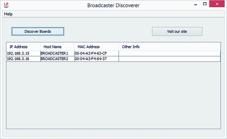
To start listening your favorite music, all you need is a board, connect it to your Ethernet network and switch it on. By logging in the appropriate web pages (to find all the connected devices, just use the PC application written in Java Broadcaster Discoverer) you can check the device status and enable it.
Before describing some practical use cases, we would describe the possible configuration. The device can operate as a transmitter (Server) or receiver (Client), each of the two modes can be set to Unicast communications (TCP-based) or to broadcast communications (based on UDP protocol). It follows that there are four main working modes. Additionally, as anticipated before, the device is compatible with VLC Media Player, IceCast and ShoutCast and can be programmed to function as web radio receiver or a generic audio streaming receiver.
In Unicast mode (point to point), using TCP/IP it is possible:
Single stream from a transmitter to a receiver board.
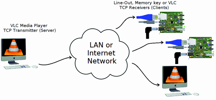
Multiple stream from VLC Media Player configured as a transmitter, to one or more board and / or one or more instances of VLC configured as receivers.
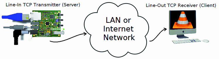
Flow from a single board transmitter to an instance of VLC as a receiver.
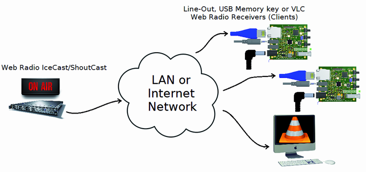
Multiple stream from a server or IceCast ShoutCast configured as a transmitter to one or more board and / or one or more instances of VLC configured as receivers (web radio).
In broadcast mode or point-to-multipoint, then using the UDP protocol, you can:

Multi-stream in the local network by a board configured as a transmitter to one or more board and / or one or more instances of VLC configured as receivers.
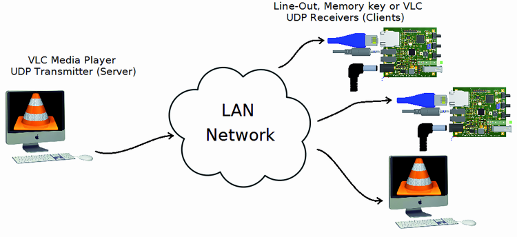
Multi-stream in the local network by an instance of VLC configured as a transmitter to one or more board and / or one or more instances of VLC configured as receivers.
Board Configuration
In order to select the desired operating mode it is necessary to turn a board on, connect it to your LAN, find out its IP address assigned dynamically via DHCP (can be useful the program shown in figure) and browse through the browser to the management Web page hosted by board.
The first web page is public, so accessible without login; the configuration pages are protected by username and password. For security you can assign two roles, the user and the administrator: the former can view all the settings and start or stop a communication, while the admin with higher privileges can change every board parameter including the network setup.
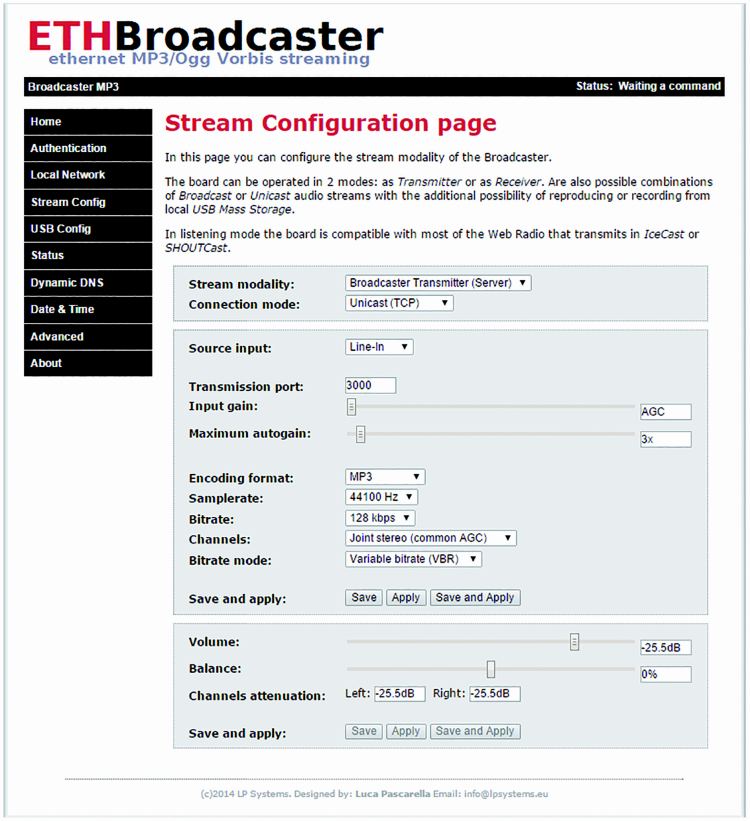
To set a working mode it is necessary to change the “Stream config” menu item as visible in figure. At every change to “Stream modality and Connection mode” settings, the page dynamically changes the parameters list to be modified accordingly. For this, you need to use a browser supporting HTML5 and JavaScript.
The first field, Stream modality, allows you to set the receiver or transmitter role (named also client or server). The second field, Connection mode, allows you to select the network protocol: TCP allows you to establish a point-to-point connection, while UDP broadcast within a local network.
When the board is configured as a transmitter, as in figure the web page will allow you to select the audio source to be transmitted which can be the Line-In input or any .mp3 files present on the USB pen-drive. When the analog input is selected (Line-In) it is also possible to choose the compression type (MP3 or Ogg Vorbis), the quality, bitrate and the input amplifier gain, so you can capture both weak and strong signals.
The last parameter is Transmission Port, which together with the IP address assigned to the board is a fundamental value to be used by receivers to create an audio connection matching between the transmitter (server) and receiver (client).
To apply changes, you can press three buttons that have the following effect:
- Save, Saves in memory the new parameters, leaving unaffected the running ones, so if you make changes to a working connection this will keep on operating until the next reboot (when the new parameters will become effective);
- Apply, It allows test setting without losing those stored in memory, so restarting the board the temporary value will be lost in favor of the stored one;
- Save and Apply, a single step configuration. If a connection is already established, this will be rebooted and the new parameters will be activated
In order to configure a board as a receiver, you have to set the stream modality field to Broadcaster Receiver (Client). In this case, the web page will show the new parameters including the output channel selection that will be:
- Line-Out
- USB
- Line-Out and USB
You must set also: Remote address, which is the remote board IP address or a web server URL, remote resource, which in case of web radio or VLC transmitters is the resource request (named path), and Remote port is the port number set on the transmitting device.
The page will also display:
- Auto-connection: when enabled, sets the automatic board connection at power up.
- Reconnection times: the number of reconnecting attempts in case of lost connection, it can be disabled, a value between 1 and 50, or unlimited;
- Reconnection delay: time to wait before trying a reconnection
- Connection timeout: represents the upper time limit beyond which a delay will be considered as a connection drop.
Finally the Bass and Treble controls allow you to change the bass or treble gain.
In order to achieve a better flexibility, you can use the board in combination with VLC Media Player. In that case, you need to set VLC as a transmitter or as a receiver.
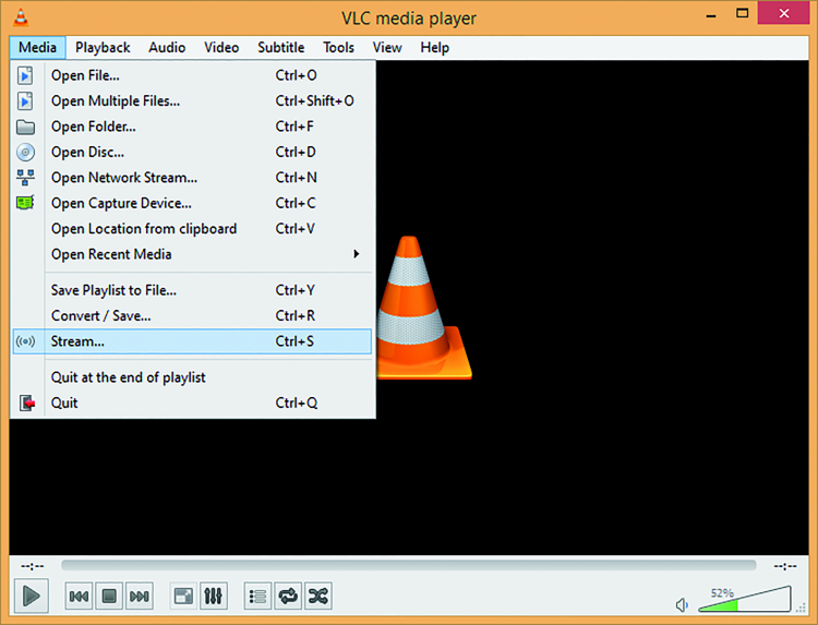
First, we see the case in which VLC will function as a transmitter. Start VLC and select Stream … from the Media menu (shortcut Ctrl + S) first figure, then you must select the audio files to be transmitted and click on Stream in second figure.

Now a new dialog box will ask you to continue with the configuration.
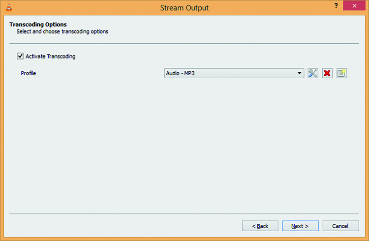
To select the point to point mode compatible with our board it s important to select HTTP as New destination: after clicking the Add button in previous figure, you create a new HTTP tab from which you can select the transmission port and optionally assign a name to the resource or leave / (slash). The transcoding activation allows you to change the audio codec; it currently supports two formats, Audio – MP3 and Audio – Vorbis (Ogg).

Second, to set VLC as a point-to-point receiver, start VLC, click Open Network Stream … from the Media menu (shortcut Ctrl + N) and enter the remote resource URL, which in this case coincides with the IP address and port number assigned to a board. The protocol must be HTTP for IceCast and ShoutCast compatibility, just as in figure.

Like in the previous cases, VLC can be configured to broadcast (transmit or receive) on a local network using the UDP protocol.
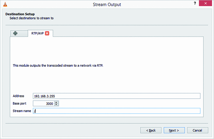
The procedure for configuring the player as transmitter will be: start VLC, click on Stream…, add the RTP Audio / Video Profile as in figure and configure it.
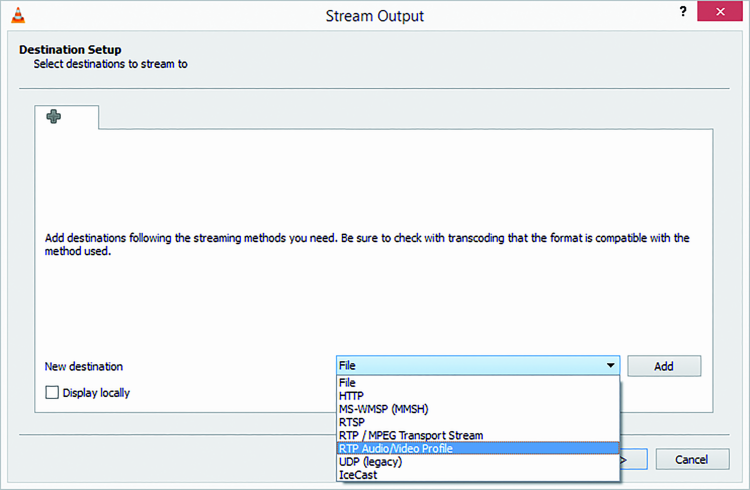
In this case to make sure that all the LAN connected devices can receive the audio stream it is necessary to select the network broadcast address (ending with 255): for instance if the board receiver has IP address 192.168.3.15, you must enter 192.168.3.255 in the proper VLC setting, just as in figure.
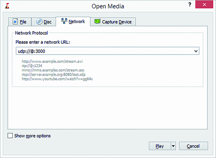
Finally the procedure to configure VLC as a broadcast receiver is: Start VLC, select Open Network Stream … from the Media menu (shortcut Ctrl + N) then:
- To listen a broadcast stream coming from a board transmitting over UDP, you must enter the remote URL udp://@:3000 like in figure.
- To listen a stream coming from another VLC instance, broadcasting over UDP, the right remote URL is rtp://@:3000
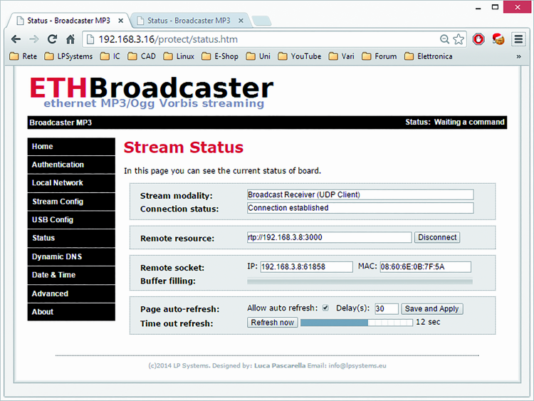
Board status
To know the board status or manually give a command you can check the Stream status page shown in figure.
On Remote resource, you will find the Connect or Disconnect button if operating as a client or Listening or Disconnect if acting as a Server.
Page Auto-refresh allows you to refresh the connection results with a specified timing so that you can always see the latest status without having to reload it manually.
Connection and disconnection can be performed by pressing the middle button too.
The left and right buttons respectively allow you to change the volume value without changing the value stored in memory.
From openstore
Ethernet MP3/Ogg Vorbis Broadcaster

Related Posts


7 Comments
Leave a Reply
-
 Arduino ISP (In System Programming) and stand-alone circuits
We use an Arduino to program other ATmega without...
- Posted 12 years ago
-

-

-
 GSM GPS shield for Arduino
Shield for Arduino designed and based on the module...
- Posted 12 years ago
-
 Small Breakout for SIM900 GSM Module
Some post ago we presented a PCB to mount...
- Posted 13 years ago
-
 Building a 3D Digital Clock with Arduino
Project to create a digital clock consisting...
- Posted 3 months ago
-
 Acoustic amplifier – in DIY Kit
This kit creates a microphone amplifier with an output...
- Posted 4 months ago
-
 Creating a controller for Minecraft with realistic body movements using Arduino
Project of a controller that maps body movements...
- Posted 4 months ago
-

-
 Holographic Christmas Tree
Beautiful project to create a Persistence of Vision...
- Posted 5 months ago
Pingback: Exploring the Open Source Ethernet Broadcaster | Open Electronics
Pingback: Open Source Ethernet Broadcaster - Electronics-Lab