- Building a 3D Digital Clock with ArduinoPosted 3 months ago
- Creating a controller for Minecraft with realistic body movements using ArduinoPosted 4 months ago
- Snowflake with ArduinoPosted 4 months ago
- Holographic Christmas TreePosted 4 months ago
- Segstick: Build Your Own Self-Balancing Vehicle in Just 2 Days with ArduinoPosted 5 months ago
- ZSWatch: An Open-Source Smartwatch Project Based on the Zephyr Operating SystemPosted 6 months ago
- What is IoT and which devices to usePosted 6 months ago
- Maker Faire Rome Unveils Thrilling “Padel Smash Future” Pavilion for Sports EnthusiastsPosted 6 months ago
- Make your curtains smartPosted 7 months ago
- Configuring an ESP8266 for Battery PowerPosted 7 months ago
A Mini Microphone Preamplifier

In this post we’ll cover the design of a microphone preamplifier, something always useful when dealing with audio applications.
This Mini Microphone Preamplifier could be used as the first stage to amplify any audio signal. The device is equipped with a microphone plus clips to be connected to a 9V battery. Amplification is achieved by using an operational LM741 amplifier. The volume level could be adjusted via a trimmer.
We will analyze what are the steps to calculate the values of the components that compose the circuit and how these values affect the characteristics of the device itself. In particular we will see how it is possible to determine the level of amplification (which is 480-fold, 53.6 dB) and the cutoff frequency (87 KHz).
The circuit itself is pre-amplifier and comes equipped with a microphone that picks up the signal. This is amplified about 480 times by using a common operational amplifier.
We emphasize that the module is a preamp: before being connected to a speaker the signal requires an additional pass through a power amplifier stage. Why then you should use a preamp? Mainly because it brings the advantages from the point of view of cleaning of the audio signal (with a better signal/noise ratio or SNR). Furthermore it’s also not possible to directly connect a microphone to a power amplifier, but it is always necessary to use a preamp like this.
Among the use cases, the module designed can be joined, for example, to camera that is not audio equipped. If you installed it inside a building and you want hear the sound as well as see the images, you can set the preamp and connect it to the same screen used to display the video signal. The device can in fact be connected to the SCART socket of a television set (in particular to the BF channels, see the box). The circuit is incredibly small so that it can also be coupled with microcameras.
Diagram
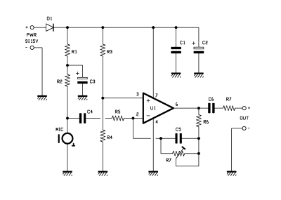
The circuit requires a power supply between +9 and +15V as we‘ll see below, a higher voltage will result in a higher level of amplification. This voltage provides power to the U1 chip (LM741) and serves to polarize the microphone (MIC). The polarization of the mike is realized through R1 and R2 resistors: a C3 capacitor is added between the two so as to further stabilize the polarization (in a sense, it acts as a small battery, if the input voltage undergoes slight fluctuations, C3 provides the energy necessary to maintain the stability). C1 and C2 perform the same operation, but in this case for stabilizing the power supply of U1.
The amplification stage itself is realized by U1, an operational amplifier. This is configured in inverting mode (the signal to be amplified enters via the V- terminal) and in single-supply configuration, we see what it is. Generally operational stages are made to work using a dual power supply (by providing both +Vcc and –Vcc). instead in our circuit U1 is connected to +Vcc and ground. Choosing this configuration it is necessary, however, to connect the V+ terminal to a voltage that is equal to Vcc/2 (this is accomplished by the divider consisting of R3 and R4).
In this way the operation of the circuit is similar to what happens using the dual power supply, where the + terminal is grounded, that is, to “halfway” between +Vcc and -Vcc. We do this since, using the single power supply, is easier to realize the circuit, as it is possible to use a single 9V battery. Continuing the analysis of the circuit, let’s see C4 and C6. C4 is used to block the DC component of the input current while C6 is used for the same reason, but in this case to block the DC component that would go to the RL load (remember while in DC a capacitor is equivalent to an open circuit).
Now let’s analyze the amplifier stage. Forgot C4 and C6 for a while: this is composed by U1, R5, R6 and R7 resistors (R7 is a trimmer) and the C5 capacitor. We want to calculate the input/output characteristic of the circuit, the ratio between the output voltage (indicated by Vout; measured to terminal 6 of the operational amplifier) and the input (indicated by Vin; measured at the input of R5).

As we have saw above the circuit behaves as if the Vterminal+ was grounded, the operational therefore leads also V- terminal to ground. In R5 then flows a current (let’s dub it I) given by I = Vin/R5, turning “right” in the circuit diagram. This current cannot enter the V- terminal (the operational presents infinite impedance), then goes across the network consisting of C5, R6 and R7. This network has a Z impedance given by the series between R6 the parallel between C5 and R6 and R7 (Z = R6 + (R7 /C5)).
Carrying out the calculations:
R6+R7+SC5R6R7
Z= —————————
1+SC5R7
The I current by passing through the Z impedance creates a voltage drop equal to I*Z. Being the terminal V- grounded, this voltage drop is now the Vout level, but changed in sign. We can then write that:
Vin R6+R7+SC5R6R7
Vout= – —— * —————————
R5 1+SC5R7
which equals to:
Vout R6+R7 1+(SC5R6R7/(R6+R7))
—— =- ——— * ——————————
Vin R5 1+SC5R7
The input / output characteristic of this amplifier is then given by the formula:
R6+R7 1+(SC5R6R7/(R6+R7))
– ——— * ———————————
R5 1+SC5R7
The first term (R6 + R7)/R5 represents the gain when frequency is almost zero (remember that properly zero frequency is blocked by C4). If we substitute the values indicated in the assembly plan, you’ll get an amplification of about 480. Then, by varying the values R5, R6 and R7 is it possible to modify the amplification rate of the circuit. We provided R7 as a trimmer to allow gain tuning.
Please note, however, that the operational amplifier cannot provide an output voltage that is greater than about Vcc-1V; if you increase the amplification over that threshold, the operational amplifier is no longer able to follow the output, thus obtaining a distortion of the signal. To increase the amplification you can increase the Vcc power supply level: do, however, note that if you exceed the +15V you could damage the chip.
Let’s look at the second term of the input/output function: this takes into account how various the gain of the device changes according to the input signal frequency. The S term is indeed related to frequency by the relation S =2f, where f stands for the frequency. We define the values of that put the numerator to zero as zeros; poles instead are the f values that pose the denominator to zero.
In our case, we get a zero at the frequency:
R6+R7
f1= ————————
2C5R6R7
and a pole at the frequency:
1
f2= ——————
2C5R7
then substituting the proposed values, you’ll get a zero at f1= 4.17 MHz and a pole at the f2= 87KHz.
Why are these poles and zeros important? Essentially because the gain of the circuit start increase from f1 frequency and start to decrease at f2.
Since f2 (pole) is much less than f1 (zero), the circuit behaves as a low pass filter with a cutoff frequency of 87KHz.
Note that, as for the gain at frequencies close to zero, the poles and zeros depend on the values of R6, R7 and and C5. Then by varying these components is also possible to vary the cutoff frequency of the low pass filter: for example if you wanted to increase the bandwidth a decade you should set f2= 870KHz and then calculate the values of the parameters accordingly. Unfortunately this is not so simple: by varying R6 and R7, also the component of the gain that that is independent from frequency changes. It is therefore necessary to do some attempts to find the right value set.
Summarizing: the amplification of the circuit is made of frequency independent constant gain term (480), plus a term that shows up at 87KHz and decreases the gain, and a term that is activated at a 4.17 MHz that instead increases the gain.
BOM
R1: 1 KOhm
R2: 1 KOhm
R3: 10 KOhm
R4: 10 KOhm
R5: 1 KOhm
R6: 10 KOhm
R7: 470 KOhm trimmer
R8: 1 Ohm
C1: 100 nF
C2: 100 μF 25VL
C3: 100 μF 25VL
C4: 220 nF
C5: 3,9 pF
C6: 220 nF
D1: 1N4007
U1: LM741
MIC: microphone
In the store
http://store.open-electronics.org/Mini_Microphone_Preamplifier

Related Posts


8 Comments
Leave a Reply
-
 Arduino ISP (In System Programming) and stand-alone circuits
We use an Arduino to program other ATmega without...
- Posted 12 years ago
-

-

-
 GSM GPS shield for Arduino
Shield for Arduino designed and based on the module...
- Posted 12 years ago
-
 Small Breakout for SIM900 GSM Module
Some post ago we presented a PCB to mount...
- Posted 13 years ago
-
 Building a 3D Digital Clock with Arduino
Project to create a digital clock consisting...
- Posted 3 months ago
-
 Acoustic amplifier – in DIY Kit
This kit creates a microphone amplifier with an output...
- Posted 4 months ago
-
 Creating a controller for Minecraft with realistic body movements using Arduino
Project of a controller that maps body movements...
- Posted 4 months ago
-

-
 Holographic Christmas Tree
Beautiful project to create a Persistence of Vision...
- Posted 4 months ago
Pingback: Mini preamplificador de micrófono | Automatismos Mar del Plata