- Building a 3D Digital Clock with ArduinoPosted 3 months ago
- Creating a controller for Minecraft with realistic body movements using ArduinoPosted 4 months ago
- Snowflake with ArduinoPosted 4 months ago
- Holographic Christmas TreePosted 4 months ago
- Segstick: Build Your Own Self-Balancing Vehicle in Just 2 Days with ArduinoPosted 5 months ago
- ZSWatch: An Open-Source Smartwatch Project Based on the Zephyr Operating SystemPosted 6 months ago
- What is IoT and which devices to usePosted 6 months ago
- Maker Faire Rome Unveils Thrilling “Padel Smash Future” Pavilion for Sports EnthusiastsPosted 6 months ago
- Make your curtains smartPosted 7 months ago
- Configuring an ESP8266 for Battery PowerPosted 7 months ago
3Drag: the Open Electronics way to RepRap
NEWS! Access the schematic of the printer here on the Rep Rap Wiki
Few months ago, after long months of testing, assembling and disassembling, print trials,and countless sleepless nights we finally decided to give birth our interpretation of the RepRap project.
First steps
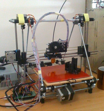 When we picked up the first RepRap kit, an elaboration of a Mendel, we spent the first couple of days to navigate between videos, screws, threaded rods and bolts: it wasn’t difficult, but surely the assembly was not so obvious and linear.
While the Prusa Mendel, the reference model and most “popular” RepRap version, can count on a myriad of mechanical parts, accessories and modifications that can be used from scratch, other RepRaps – with variations and changes in the structure – always require an assessment of the applicability of this or that changes you find online.
In light of our experience, we started planning our version of Mendel with three simple goals: ease of installation, Prusa Mendel comparable performance, 100% compatibility with RepRap electronics, firmware and software.
After two months, the light
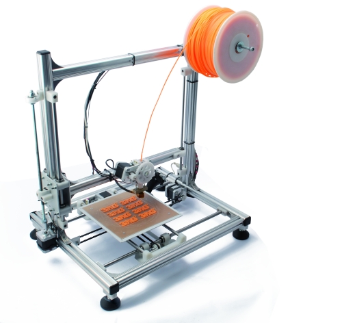
Pursuing simplicity of assembly led us to abandon molded plastic parts and M8 threaded rods and switch to aluminum profiles with shapes designed with fixing parts in mind.
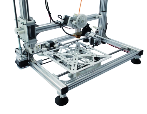
In exchange for this very stable structure that you can assemble with simple sequences, our printer is not “compatible” with the world of RepRap mechanical tweaks. Each part is designed to be light where needed, such as with the plate drive system, and rigid to suppress vibrations and unwanted resonances.
Compared to a Mendel, our printer uses the X/Y the plate and Z for the dolly. This allowed us to simplify the extrusion system that no longer have to move on a horizontal axis: is simply attached to the structure that moves along the Z axis.
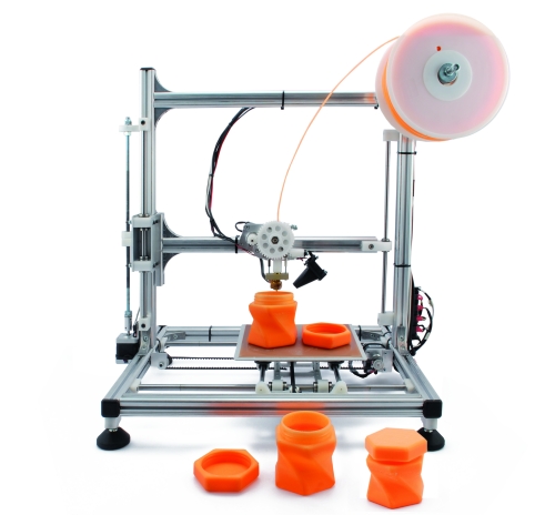
The printing plate support, then, is designed to accommodate a “base” of epoxy glass that combines good adhesion with the PLA, dimensional stability and it’s quite cheap. The surface of the epoxy glass base must be treated with fine sandpaper to expose the fiberglass. From our trials you get a smooth matte finish along with an excellent grip, even with pieces of a certain size. Compared with many other solutions we tested during experimentation, this is proving to be the most interesting solution with PLA prints. The dimensions of the support, however, are suitable for mounting of a Prusa floor heating standard solution (about 21 x 21 cm) on which you can set a printing plate provided that this is not too heavy. One of the first prints made with our printer, it is worth to mention, is the half Eiffel Tower that was carried out at approximately 85 mm per second with a vertical height of about 20 centimeters. The result has left us amazed at first, because from an initial setting of a 60(120) mm/sec in printing(moving), we realized we’d left a speed increase of 140% on Repetier-Host. Nevertheless, the entire structure was almost perfect, with fine detail and precision in elements positioning. The image of the molded part is still more than a thousand words.
Finally kit are available.
With the results achieved, and after few more months of refinements, we can finally release our mechanical interpretation of a RepRap we think of ourselves not exempt from offering everything in a practical and complete kits.
As said, electronics are fully compatible with the firmware and software from RepRap world. This will allow you to upgrade your printer with the new firmware and software solutions that gradually people will be able to create to make 3D printing easier and more intuitive.
The Marlin firmware is provided configured to reflect: the mechanical characteristics of the belts, the position and the direction of rotation of the motors and the connection type of the of Home (0,0,0) positions detection microswitches. Using a 0022 or 0023 Arduino IDE you can reprogram the board with all the simplicity of a single click of the mouse.
Marlin, moreover, can be reconfigured in a simple manner by intervening in the source file “Configuration.h” which contains all the functional parameters and mechanics characteristics. To make the printing and adjustment simpler and more repeatable we have combined the microswitch a series of screws which allow fine adjustment of each zero position. This is not an automatic adjustment, but once you have adjusted the screws in the correct way, you will have a steady and reliable positioning.

Related Posts


15 Comments
Leave a Reply
-
 Arduino ISP (In System Programming) and stand-alone circuits
We use an Arduino to program other ATmega without...
- Posted 12 years ago
-

-

-
 GSM GPS shield for Arduino
Shield for Arduino designed and based on the module...
- Posted 12 years ago
-
 Small Breakout for SIM900 GSM Module
Some post ago we presented a PCB to mount...
- Posted 13 years ago
-
 Building a 3D Digital Clock with Arduino
Project to create a digital clock consisting...
- Posted 3 months ago
-
 Acoustic amplifier – in DIY Kit
This kit creates a microphone amplifier with an output...
- Posted 4 months ago
-
 Creating a controller for Minecraft with realistic body movements using Arduino
Project of a controller that maps body movements...
- Posted 4 months ago
-

-
 Holographic Christmas Tree
Beautiful project to create a Persistence of Vision...
- Posted 4 months ago
Pingback: Stampante 3D | Pearltrees