- Building a 3D Digital Clock with ArduinoPosted 3 months ago
- Creating a controller for Minecraft with realistic body movements using ArduinoPosted 4 months ago
- Snowflake with ArduinoPosted 4 months ago
- Holographic Christmas TreePosted 5 months ago
- Segstick: Build Your Own Self-Balancing Vehicle in Just 2 Days with ArduinoPosted 5 months ago
- ZSWatch: An Open-Source Smartwatch Project Based on the Zephyr Operating SystemPosted 6 months ago
- What is IoT and which devices to usePosted 6 months ago
- Maker Faire Rome Unveils Thrilling “Padel Smash Future” Pavilion for Sports EnthusiastsPosted 6 months ago
- Make your curtains smartPosted 7 months ago
- Configuring an ESP8266 for Battery PowerPosted 7 months ago
Let’s Build an open source Quadcopter – Part1
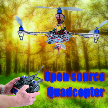
A high performance multirotor copter that may be created by starting from a premade base and an Arduino Mega based board, that may receive the commands from a model aircraft’s remote control, and that supports telemetry via smartphones.
Nowadays most people call “drone” something that is, actually, a multicopter whose most common form is “incarnated” by the quadcopter. Generically, a drone is a robot, but war zones news accustomed us to use the word “drones” to describe those aircrafts that are capable of autonomous flight. The related technology was born – as many others – for military purposes, but it became available for everyone and started to become a commercial fact, and it passed under the more generic term of UAV(Unmanned Aerial Vehicle). As with all the commercial phenomenons, it slipped in the consumer’s sector, along with the “toys” that inundated the stores all over the world. Nowadays the applications for civil purposes are various: from video surveillance to video shoots in areas that are closed off to people, and up to the analysis of agricultural crops by means of special video cameras. It is now possible to also make 3d reliefs of a whole territory, and it became a useful tool even for the civil protection.
The interest towards these aircrafts and above all towards the radio-controlled models of this kind, brought us to propose – not just the review of a commercial product, but – a veritable quadcopter project, that is to say a RC model supplied with four propellers, placed at the vertices of a cross, each one of them being activated by an electric motor; the whole being managed by an electronic board of which we will describe the circuit diagram and the construction in these post.

The control board
In order to manage the quadcopter’s engines we created a generic control board for multirotor copters (and RC models in general) that we named Fly Control board; it supports command software such as MultiWii and MegaPirateNG. Our board’s features are:
- ATMega 2560 microcontroller;
- support for MegaPirateNG and MultiWii firmware;
- up to eight outputs for the engines;
- 8 inputs for standard RC receivers, and compatible with PPM receivers;
- four serial ports for debug/Bluetooth Module/OSD/GPS/telemetry purposes;
- three servo outputs for the control of a gimbal system (pitch, roll, trigger);
- I²C-Bus for the addition of sensors and devices;
- connector for a GPS module;
- it is compatible with IMU GY-521, GY-86 modules and external ones;
- connector for a FTDI USB/serial converter.

The circuit diagram is a very simple one, since the board is simply a collector for all the elements that depend on the ATmega microcontroller that is assigned to their management. Its heart is the Atmega2560, the same found in the Arduino Mega boards; a 3.3V power supply stage is there as well, for possible additional devices. The rest of the hardware is a set of connectors and signal LEDs. In addition to the microcontroller, the other crucial element is the IMU (Inertial Measurement Unit, that is to say the platform detecting acceleration, movement on the three axes, etc.) module that we preferred not to directly implement on the board; instead we supplied a dedicated connector on which to insert the desired module; this will allow you to use even IMU modules that are more recent in comparison to the one we presented here. Both the board and the software support different flight configurations: from simple aircrafts to multirotor copters.
The flight software
As soon as the conditions were met, many enthusiasts proposed different solutions for the flight software, that was later developed also thanks to the contribution of the Internet community; we will briefly see the story of these applications, that started some years ago now. In the beginning there was Ardupilot for ATmega328P, which evolved in Ardupilotmega for ATmega2560 (abbreviated as APM) and that we used for an autonomous aircraft project in March 2011. In the beginning they were little more than shields based on Arduino, to which the IMU was added, but later they became complete boards (AIO all in one), completely independent from Arduino boards.
The project is now a commercial one and merged into a single website, which is supported by a specific online store. The project considers different pieces of software and hardware, depending on the fact that you might want to control multicopters, airplanes or cars; even the Arducopter project, that started at about the same period, was finally absorbed by Ardupilot in 2013. Despite the evolutions (specially from the commercial point of view), it is still an open source project (but with some limitations) and therefore both the hardware diagrams and the software sources are available; moreover the software to be loaded on the board and the Mission Planner – a navigation planning software – are available. The firmware for the board is a complex one as regards the installation, since it has many additional libraries for which the whole Arduino IDE (a modified one) is downloaded, along with various related dependencies for a total of 90 MB.
In the store, every kind of peripheral you may imagine is available, and the development of a dedicated app for the management via smartphone is currently underway; it will use the standard communication protocol, mavlink.
MegapirateNG is a “branch” of the APN project and it has been thought so to run on different platforms: it is completely OpenSource and compatible with APM.
The firmware running inside the board is not among the simplest ones: in addition to the flight stabilization there is the management of alarms, of telemetry, of position and much more, for such a reason we preferred to use an already existing software, named MultiWii, that is a completely open source one and that was developed in the last years, also thanks to the contribution of the enthusiasts in the Internet. It enables the control of multicopters, helicopters and aircrafts; the reference website.

The project was born with the usage of a Nintendo Wii Motion Plus gyroscope (the cheapeast and easiest to find at the time) and an Arduino mini pro board, but now it supports a great number of sensors and boards. The firmware is a very light one and may run on a small Atmega 328, but with all the functions activated (navigation and GPS) it is necessary to use an Atmega 2560. The software is managed in the site. By downloading the software package you will have the software for Arduino and the GUI available, it is written in Processing and meant to be run on a PC, so to manage the settings and the telemetry. The software for Arduino uses only system libraries and therefore its usage is an immediate one, having only Arduino IDE available. In order to configure the board and use the telemetry and the mission planning, the WinGui software is also available, as well as an application for Android smartphones.
Since the MultiWii project is a completely open source one, the control board’s circuit diagrams and all the information concerning its usage are easily available. The full possibility of configuring the software allows to adapt it to the various boards that are already assembled and ready-to-use, as proposed by other subjects. In this article we present our experience in creating a class 450 quadcopter (the distance from engine to engine is 45 cm) and we will describe all the stages concerning the creation and the activation, in the simplest and clearest way possible, even though the project is complicated in itself, given that it involves different aspects of mechanics, electronics and information technology.
The required hardware
When building a quadcopter from scratch, the choice of the materials becomes an essential subject, to which to pay the greatest attention: each component must interact with all the others in an entirely perfect way and nothing must be left to chance. We oriented ourselves towards common components, and not excessively expensive ones, that are distributed by the our online store. The list is in Table 1. As an alternative to the FTDI converter, you may use the 5V FTDI USB-Serial, labelled with the 6168-FTDICABLE5V code, and still sold by Futura Elettronica.
Table1

The propellers used for our multicopter’s propulsion are of the simple plastic kind: they are the cheapest ones; their light flexibility enables them to absorb small shocks, at the price of a lesser efficiency. The filled plastic propellers (such as the APCs, for example) are more rigid and offer better performances; those in carbon are very light and rigid, and are however very delicate, since even a small shock may break them.
We would like to remind you that the quadcopter absolutely must not fly if a propeller is cracked or chipped, and anyway that you must never try to repair a damaged propeller, since a part may detach itself and hit someone, with the resulting consequences that might even be serious ones.
Bootloader loading and board testing
If the board’s microcontroller’s is lacking a bootloader you need to load it; for the purpose you may use a dedicated programmer or, more simply, an Arduino board acting as a programmer. In the latter case please check Table 2 so to learn of the connections to be made between the programming board and ours.
Table2

MultiWii configuration
Even if our board supports both Multiwii and MegaPirateNG, in this article we will describe only the first one of the two in detail; given that Multiwii is for a general usage, we need to configure it before loading it on the board. For the purpose, please load the last Multiwii version from website (in our case, it is version 2.4) and after having unpacked the package, please open the MultiWii.ino file. Please go to the config section and search for the code line #define QUADX and remove the two comment characters, “//”; after that please do the same with the #define GY_86 line or with the #define GY_521 one, depending on the IMU module you wish to use.

Once this has been done, please proceed with the following configurations: the Multiwii failsafe monitor is a form of protection that – in the case of contact lost with the receiver – prevents the quadcopter from advancing. The function cyclically verifies the presence and integrity of the signal coming from the remote control’s receiver and if the value exceeds the extreme limits of 1,000 and 2,000 it activates the failsafe. As soon as the failsafe is detected, the software will try to avoid the crash by keeping the quadcopter stabilized by means of the internal sensors and by gradually cutting off power from the motors, for the landing. The failsafe may be activated by taking off the comment marks in the #define FAILSAFE line. As soon as you are operational, you may carry out a test, by turning off the radio and by verifying the quadcopter’s behaviour. It is possible to enable a buzzer that will acoustically warn about the operating state; you need a buzzer having an electronics that is compatible with a 5V power supply, to be connected to the board at the contacts marked as buzzer, and please be careful with respecting the polarity.

In order to activate this function please delete the comment characters from the #define BUZZER line in the config.h file.
The acoustic warnings consist in a sequence of three beeps having a variable duration, that depend on the operating state. The durations of the beeps and of the pauses are defined as follows:
- N = None (0 ms);
- S = Short (50 ms);
- L = Long (200 ms);
- D = Double (2.000 ms).

Each warning has different priorities: the first ones have a greater priority and are:
- Failsafe find me signal: LNN,D (repeat);
- Failsafe landing active: SLL,S (repeat);
- GPS RTH/ PH activated without fix: SSN,S (repeat);
- Beeper: SSS,S (repeat);
- Runtime Warning: SSS,N (repeat) (#define ARMEDTIMEWARNING);
- Battery voltage warning level 3: SLL,D (repeat);
- Battery voltage warning level 2: SSL,D (repeat);
- Battery voltage warning level 1: SLN,D (repeat);
- RCoptions Toggle: S (#define RCOPTIONSBEEP).
Additional acoustic warnings have been provided, that is to say:
- Inflight ACC calibration activated: SS (#define INFLIGHT_ACC_CALIBRATION);
- Inflight ACC calibration deactivated: SSS;
- Gyro calibration done: SSS;
- ACC calibration done: L;
- LCD Configuration step: S;
The board provides the A0VB input for the reading of the battery voltage; by means of a voltage divider, the voltage is then adjusted to the microcontroller’s power supply voltage.
In order to use this function you have to remove the comment characters on the #define VBAT line of the config.h file and to modify the following line like this:
#define VBATSCALE 102
From the battery’s positive pole please provide a connection towards a female connector to be connected to the board’s AOV input; as for the ground wire the GND of the ESCs will be used.

The gyroscope is the main sensor and the only essential one: thanks to it, it is possible to compensate possible rotations with respect to the three axes and therefore to prevent that the quadcopter spins around itself or that it turns upside down. The gyroscope suffers from a deviation that in time prevents from knowing the absolute angle of the vehicle; for this reason the gyroscope alone does not allow to keep the quadcopter perfectly levelled to the ground. The accelerometer takes care of this problem, by supplying an absolute angle for the bearing and by guaranteeing that the quadcopter remains horizontal, and avoids that it may slip towards some direction. Unluckily, the gyroscope – and even more, the accelerometer – that we use (they are MEMS) are influenced by vibrations and, as you will see, we will have to take them into account. In order to better the stability it is possible to filter the values acquired by the IMU module, especially if there are still vibrations, and notwithstanding all the precautions placed in the mechanic construction; the line on which to act is the following one:
#define GYRO_LPF_98HZ
of the usual config.h file. By further lowering the software filter’s cutoff frequency, even more cleaner readings are obtained, but they are not fast enough for those who want an aerobatic flight.

The magnetometer measures the feeble earth’s magnetic field, so to determine the geographic north, a measurement that enables to keep the quadcopter always oriented towards the same direction, and it is an essential function for the GPS navigation. The magnetometer, however, determines the magnetic north, which differs from the geographic north because of the magnetic declination: things get more complicated by the fact that the latter changes in time. The magnetic declination is therefore the angle between the direction of the magnetic north and the geographic one; in order to know its value in the point where you stand you may use the service offered by the website. Once you have set your position, the website will give you the magnetic declination, expressed in degrees and minutes (and with a sign) that you will have to convert in degrees by means of the following formula:
degrees+(minutes/60)
Once you will have done this, please go to MultiWii’s config.h file and modify the #define MAG_DECLINATION 4.02f line by inserting the value you just obtained: if the declination is a negative one you need to add a “-” before the number. Please leave the “f” after it anyway. The magnetometer is very sensitive to the magnetic fields and it is also influenced by the cables in which high currents are flowing (such as those used in order to power the ESCs); therefore if you notice that – when you activate the engine acceleration – the angle of the quadcopter varies excessively, you will have to intervene by distancing as much as possible the IMU module’s power supply cables, that is to say you will have to wrap them up in some tinfoil. Please remember that before any measuring you will have to calibrate the sensor.

The IMU GY-86 module (that is used in this project) has – in addition to a gyroscope, an accelerometer and a magnetometer – a barometer that is suitable for measuring the atmospheric pressure. From the measure of the pressure at ground level and higher up it is possible to determine the aircraft’s height which is however influenced by the temperature and by every pressure variation (weather conditions) that occurs after the sensor’s calibration.
In the case of the quadcopter, the sensor is used so to keep automatically a predetermined altitude; in fact in order to keep a constant altitude it is needed to act continuously on the engine acceleration and to compensate continuously the battery’s loss of power. To entrust this to an automatic function helps quite much and becomes essential when flying with the help of the GPS.

Given that the sensor is strongly influenced by air turbulences that are created by the propellers, it is essential to provide a cover that protects it: for the purpose you may use the sponges used in order to reduce the wind’s influence in the microphones (they may be bought as replacements). Even in this case you may carry out a simple test, thanks to the data from the telemetry: if the reading of the altimeter suffers from too many disturbances, when activating the gas, it is the case to carry out a shielding. In order to have some clean readings you will have to distance the power distribution board (PDB) as much as possible from the IMU module, and to keep the ESCs’ power supply cables very short and intertwined among them, so that the magnetic field created by the current on the positive wire is nullified by the one from the negative wire.

It is often possible to see – in some quadcopters – the usage of a GPS with an integrated compass, installed on a high tree, far from all the electric circuitry: it is not a case. The barometer is used in order to determine the height from the ground, on the basis of the atmospheric pressure, which varies depending on the altitude; the influencing factors – or those that somehow make the pressure change – are many (first among them the weather conditions), thus preventing the exact determination of the absolute height.
Such a problem is not very relevant if you are flying at a high altitude, but is a critical one if the multicopter is close to the ground: an error of some decimeters is not dramatic at 50 meters from the ground, but it makes the difference between a soft landing and a crash at one meter from the ground.
In order to obtain an accurate indication of the approach to the ground you may use a SONAR (ultrasound) module, but at the moment we write the software (V2.4) supports the height measuring via sonar only for informative purposes, and not for an integration in the control. Therefore you should modify the firmware by yourself.
IMU installation and operational testing
The IMU module that has been chosen for this project is a 10DOF (10 degrees of freedom), a very complete one, equipped with the last generation digital sensors, that are high accuracy and low noise ones. As hinted before, it includes a gyroscope, an accelerometer and a magnetometer (with all the three axes) in addition to a high sensitivity barometer. In order to mount it please weld the male strip in the IMU module, being sure that the printed circuit board’s components points upwards, once installed into the board. Please insert the IMU module in the specific connector and make sure that the connection is excellent.

In order to be sure that the IMU module does not suffer from vibrations or that it may move, it is appropriate that it is fixed to the printed circuit board; please do not use metal elements but prefer plastic ones, such as for example some small nylon screws.
Since it is the heart of the stabilization, it is of the essential importance that the IMU module is perfectly operational and calibrated, otherwise your quadcopter won’t be able to fly, or anyway won’t be able to do it in a way that meets the expectations.
Among the files of the MultiWii project, you will also find the management software, that is essential for the quadcopter’s tuning; please go to the MultiWiiConf folder and execute the MultiWiiconf.exe file, taking care of choosing the one that is compatible with your operating system, before booting it please make sure that the board is connected to the PC by means of the corresponding USB/Serial converter.

At a first impression it may appear chaotic and complicated, but you will see that you will soon become familiar with its various functions. Up and on the left you will find the commands for the serial’s management and the buttons that will allow you to save and load a setup series. On the right you will find the sensors that have been detected on the board as highlighted as well as the board’s bearing, by means of graphic animations: the accelerometer (ACC), the barometer (BARO) and the magnetometer (MAG) are there, in addition – obviously – to the gyroscope, that is the only sensor that is absolutely necessary.
As you may see, the software supports even a GPS, a sonar and an optical sensor. Down and on the left you will find the sensors’ instant value; more on the right there is a diagram with the time trend of the same ones. Please calibrate the accelerometer (CALIB_ACC) and make sure that the board remained motionless, in a perfectly horizontal position. Please calibrate the magnetometer (CALIB_MAG) by rotating the board of 360° in every direction, for at least 30 seconds. Please keep the board in front of you, with the arrow pointed onwards; by rotating it towards right and towards left, the ROLL indicator will change accordingly. By inclining the board upwards and downwards the PITCH indicator will change accordingly.

In the initialization stage, a short flashing of the LED STATUS means that no kind of IMU is connected; a long flashing means that the IMU has been detected. After the initialization, the LED STATUS will prove to be turned on when the engines are armed, and turned off when the engines are unarmed. The LED ALARM will flash in the case an alarm condition has been found.

Remote control’s activation
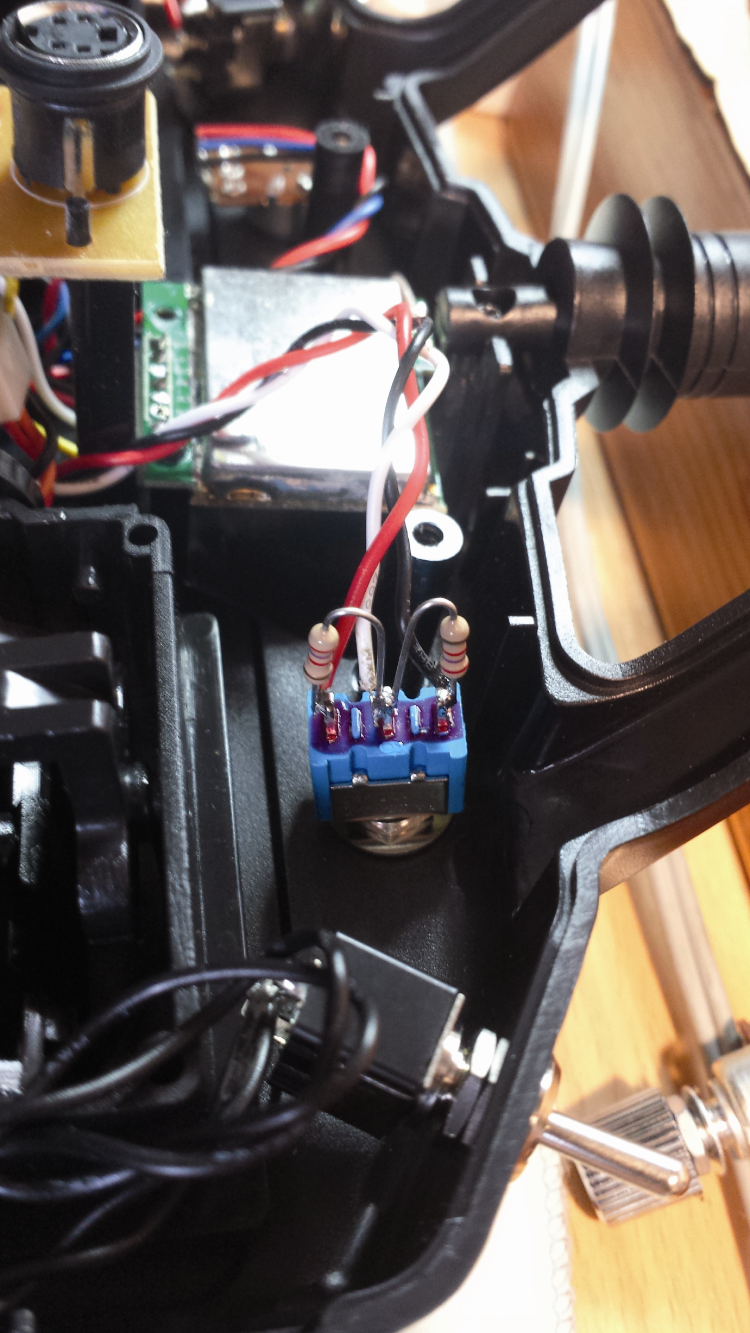
For this project we used a cheap – but anyway complete – six-channel remote control, signed as FS-CT6B. It is a remote control operating on the 2.4 Ghz frequency, in which the programming of all the functions does not occur by means of a user interface on the remote control itself, but via a specific software for PCs; all of this is to the advantage of the economy and building simplicity (that means great savings on the purchase price) since on the remote control buttons or displays are not found, but simply a multicolour LED, so to signal the battery’s charging state.
Before using it, you will have to modify the remote control, by removing the potentiometer on the left of the antenna and by mounting a 3-position unipolar deviator, to which you will connect – between the centre and the ends – two 2.7 kohm 1/4 watt resistors that will simulate the potentiometer with a halfway pointer, that may be partially bypassed by the deviator itself.

The wires that went to the ends of the potentiometer (that has been removed) should be connected to the ends of the deviator, and the pointer’s one should be connected to the central end of the same. In this way you completed the modification that – as we will see in the second installment – is needed in order to set the quadcopter’s three operating modes.
The remote control is supplied with the american-style setup, in MODE2, with that the accelerator on the left; it is possible to change this configuration by acting at a software settings’ level and by physically modifying the sticks’ settings.
The MODE2 is also the mode used on the toys, and it is therefore the most familiar one in this kind of applications.
The transmitter, the receiver, the cable for the connection to the PC and the software for Windows are included in the package: the batteries are not, however. Since the 2.4 GHz remote controls are of the multichannel kind, it is needed to associate each receiver to your own transmitter, an operation that in the technical jargon is named binding. Please make sure that the transmitter is turned off, then insert 8 Mignon batteries (also known as AA batteries) in the battery holder: it is better if they are of the rechargeable kind. Please insert the jumper (bind plug) on the BAT connector in the receiver; with the two jumpers bring the 5V power supply from the quadcopter’s board to the receiver (pins + and – of whichever channel). If you did everything correctly, the receiver’s LED will start to flash, so to indicate that it is ready for the association.
Please press and keep pressed the BIND button of the transmitter and turn it on; then wait for the receiver’s LED to remain turned on with a fixed light: this will indicate that the association has been executed correctly; after that please release the BIND button.
Please turn off the receiver, remove the jumper and connect a test servo to one of the channels, and verify by means of the remote control that everything works properly.
The correct procedure for booting the system always consists in turning on the transmitter first, and only later the receiver (in this case, the quadcopter); vice versa, in order to turn the system off please start from the receiver and turn off the transmitter last.
This prevents possible malfunctions, due to possible jamming signals that the receiver might pick up in the absence of the transmitter’s signal. Please connect the receiver to the board by using eight small cables with a female-female end, accordingly to the instructions in Table 3.
Table3

At this stage you may make the transmitter and the board operational and to analyze the data received. The Multiwii software works correctly if the signals of each channel’s radio have a range going from a minimum of 1,000 to a maximum of 2,000, with a central value of 1,500. In order to obtain this configuration it is needed to opportunely program the transmitter, and then we will use the dedicated cable (supplied in the bundle), so to connect it to the PC. The cd rom supplied in the bundle contains both the drivers and the software, that will be installed according to the normal procedures. The supplied cable internally contains an USB/Serial converter that is similar to the ones generally used along with Arduino, thus once it is inserted in the PC’s USB, the drivers will supply a virtual serial with which to talk with the transmitter.
You will have to act on the radio’s physical trimmers and on the software’s Sutrim fields, in order to center the signal on the 1500 ms and on the Endpoint field, in order to regulate the full scale of the various channels. It is essential that each channel goes under the value of 1,100 and over the value of 1,900, since many functions of the MultiWii software are implemented only if the channels exceed these limits. With the radio in our possession it has not been possible to perfectly reach this objective, therefore we had to reconfigure the MultiWii software, by modifiying the radio’s full scale values, #define MINCHECK 1100 and #define MAXCHECK 1900 as found in the MultiWii.h file.
The new values are #define MINCHECK 1150 and #define MAXCHECK 1850, while the radio has been configured with a range going from 1100 to 1900, and leaving a margin that is equal to 50.
Please remember that the values reported in the MultiWii software and related to the radio channels increase when the sticks are brought forward or moved to the right; if it wasn’t like this, please act on the REVERSE command of your radio’s inverted channel.
CONCLUSIONS
Well, for now we will stop here: in the next installment we will finish the discussion on the subject by explaining the commands and by completing the quadcopter’s hardware, in addition to dealing with the test and the maiden flight. We will end then by talking about the management modes from smartphone.
Flight glossary

PITCH: it represents the pitching, that is to say the oscillation on the transverse axis.
ROLL: also said rolling, it is the term used to define the rotation of the model on its longitudinal axis.
YAW: the movement around the yaw axis, that is to say the rotation of the model on its vertical axis.
BLADE PITCH: it indicates the inclination of the propeller’s blade with respect to the rotation plane.
CLASS: it indicates the category the quadcopter belongs to, that is identified from the transverse distance between two engines (expressed in millimeters).
ESC: the acronym of electronic speed controller, that is to say the power driver for the brushless engines.
BEC: the acronym of battery eliminator circuit, it indicates that the ESC is supplied with an internal voltage regulator.
PDB: the acronym of power distribution board, that is to say the printed circuit board that is used for bringing the battery power to all the ESCs.
MODE2: the remote control’s usage mode, with gas and yaw and the left and pitch and roll on the right.
MODE1: the remote control’s usage mode, with gas and yaw and the right and pitch and roll on the left.
BIND: it indicates the association between the remote control and the receiver as in the RC radio equipment.
PID: it indicates the triad formed by the proportional, integrative and derivative parameters of a control.
From Openstore
RC Transmitter & Receiver 6 channels 2,4 GHz
FTDI USB-serial converter- 3,3V e 5V
Extension cord for servo – Lenght 150mm
HC05 Bluetooth Transceiver – SMD module
LIPO charger and lithium-ion battery
Crius – Connection tab to power multicopter
GY-86 flight control sensor module for multicopter

Related Posts


3 Comments
Leave a Reply
-
 Arduino ISP (In System Programming) and stand-alone circuits
We use an Arduino to program other ATmega without...
- Posted 12 years ago
-

-

-
 GSM GPS shield for Arduino
Shield for Arduino designed and based on the module...
- Posted 12 years ago
-
 Small Breakout for SIM900 GSM Module
Some post ago we presented a PCB to mount...
- Posted 13 years ago
-
 Building a 3D Digital Clock with Arduino
Project to create a digital clock consisting...
- Posted 3 months ago
-
 Acoustic amplifier – in DIY Kit
This kit creates a microphone amplifier with an output...
- Posted 4 months ago
-
 Creating a controller for Minecraft with realistic body movements using Arduino
Project of a controller that maps body movements...
- Posted 4 months ago
-

-
 Holographic Christmas Tree
Beautiful project to create a Persistence of Vision...
- Posted 5 months ago
Pingback: Let’s Build an open source Quadcopter – Part2 | Open Electronics
Pingback: Construyendo un quadcopter para principiantes - Calendae