- Building a 3D Digital Clock with ArduinoPosted 3 months ago
- Creating a controller for Minecraft with realistic body movements using ArduinoPosted 4 months ago
- Snowflake with ArduinoPosted 4 months ago
- Holographic Christmas TreePosted 5 months ago
- Segstick: Build Your Own Self-Balancing Vehicle in Just 2 Days with ArduinoPosted 5 months ago
- ZSWatch: An Open-Source Smartwatch Project Based on the Zephyr Operating SystemPosted 6 months ago
- What is IoT and which devices to usePosted 6 months ago
- Maker Faire Rome Unveils Thrilling “Padel Smash Future” Pavilion for Sports EnthusiastsPosted 7 months ago
- Make your curtains smartPosted 7 months ago
- Configuring an ESP8266 for Battery PowerPosted 7 months ago
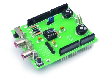
A Video Overlay Shield for Arduino
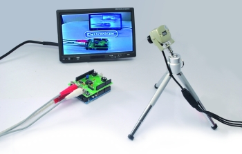
In this post we will deal with an interesting solution to overlat text on a video signal.
This solution, which uses the LM1881 integrated, has a lot of use cases accompanied by variable software challenges.
For this reason this post is a kind of tutorial, presenting no vertical solution, but instead providing an overview of the possibilities.
This shield start from an idea of nootropic
Apart from the Arduino module, the key component of the system is, as said, the LM1881 from National Semiconductor. This integrated component is designed to extract the sync information from PAL and NTSC composite video signals with positive polarity video. In this case, by increasing the voltage level of the video signal, image brightness increases. The chip requires a single power supply between 5 and 12 Volts.
The TVout library is available to simplify the code needed to use the shield.
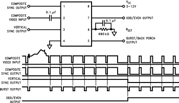
Given an input video signal pin 2, on the output pins of the integrated you’ll find:
-
pin 1 provides the video composite sync signal, the waveform of which is obtained by removing the component video from the input signal on pin 2 and leaving the sync component unchanged;
-
pin 3 provides the vertical sync signal obtained by an integration of the video composite sync signal present at pin 1. In other words the signal changes level at each half-frame, losing the information about the horizontal sync;
-
On pin 7 you’ll find a very useful signal used in digital image processing by microcontrollers; the signal changes level depending on whether the half-frame (field) in the processing is the odd or even part of the very same image.
-
On pin 5 a signal is generated whose waveform is determined by the starting impulses of the chrominance signal. These pulses are contained in the video signal immediately after the horizontal sync pulses and communicate the reference black level for the line described in the following part of the signal. This signal can be used to sample chrominance rate (starting impulses) inside the composite video signal. The resistance available on pin 6, finally, allowsthe LM1881 to refine the sampling frequency of the video signal, for sources that have a scanning frequency that is different from 15.734 kHz.
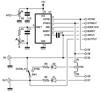
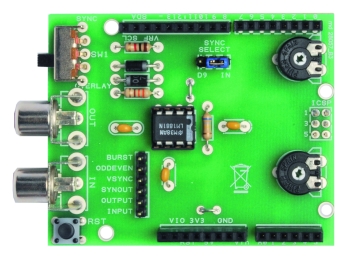
Given this premise on the operation of the LM1881 let’s look at the wiring diagram of the shield.
Pin 6 of the LM1881 is connected with a fixed resistor and a potentiometer in series so you can synchronize the integrated with the input video signal.
The SYNCSELECT jumper allows you to choose the source of sync pulse of the video signal. Normally the input video pulse signal is used. It’s possible to use the circuit also without a video input signal generating the sync pulse on Arduino’s pin 9 by the software.
The OUTPUT SELECT switch allows you to set the behavior of the shield with respect to the different possibilities to overlay text to the video signal.
The various possibilities are summarized as follows:
-
The text is superimposed on top of the video signal
-
only the video signal
-
only text
Clearly the possibilities we described must be compatible and consistent with the overall system configuration: it’s not possible, for example, to select the output as video only in case there is no input video source.
The following table describes the possible combinations.
|
OUTPUT SELECT = overlay. |
OUTPUT SELECT = sync only. |
|
|
SYNC SELECT = video input. |
Text plus video overlay |
Text only. |
|
SYNC SELECT = D9. |
NA |
Text only (there is no video signal input) |
The connections to the Arduino module are as follows:
-
D2 pin is connected to the vertical sync signal in output from LM1881 pin 3
-
D6 pin is connected to the input video signal which also goes to LM1881 pin 2
-
From D7 the output video signal is taken;
-
D8 pin is connected to the composite sync signal coming as output of LM1881 pin 1
-
the analog input A2 is connected to the POT potentiometer that allows to calibrate the brightness level to be used as a discriminating threshold during the video frame capture.
It’s now time to to describe how to use the support library TVout. We’ll describe how the library itself “sees” the video frame and how the definitions are organized and how you can use use of characters and bitmap images.
BOM
R1: 680 kohm
R2: 330 ohm
R3: 1 kohm
R4: Trimmer 1 Mohm
R5: Trimmer 10 kohm
C1: 100 nF
C2: 100 nF
C3: 100 nF
D1: 1N4007
D2: 1N4007
U1: LM1881
SW1: switch
RST: Microswitch
How it works
The video frame is seen directly as a matrix of pixels which for PAL format is around 128 for 96 pixels.
Different resolutions can be set, especially in case you want to acquire video frames to be subjected to subsequent processing. In these cases it is essential that the horizontal resolution is divisible by a eight factor (120, 136, etc..). The library applies a scale factor to readjust the resolution to the mentioned limits.
Text and bitmap placements must be expressed in pixels. In making the calculations for the construction of the video composition layout keep in mind that the the top left vertex of the video frame corresponds to the x = 0, Y = 0 position.
In our case different character maps with different sizes can be arranged: those can be used simultaneously with different graphics in bitmap format.
The library also provides a set of primitives that allow you to dynamically create recurring geometrical shapes (like lines , circles, polygons, etc.).. Alternating commands sequences animations and motion graphics can also be created.
In the library there are some default font types, characterized by the size in pixels. Font categories are defined by a fixed-width font size of 4×6, 6×8 and 8×8 pixels . To use these fonts, as we will see later, it is sufficient to include them in the program and use them with the appropriate instructions.
Besides default fonts you can use custom fonts.
You can define two types of fonts: fixed width and variable width.
Each font is represented, as in the case of a normal C library, by two files (an header file .h and a file that contains the description of the actual font format, .cpp)
Let’s see an example of the definition of a fixed format font.
The header file that we will call “font4x6.h” contains the following instructions:
#ifndef FONT4X6_h
#define FONT4X6_h
#include <avr/pgmspace.h>
extern const unsigned char font4x6[];
#endif
The. cpp file called “font4x6.cpp” must be organized as follows: the first 3 characters of the file shall contain the width and height in pixels, and the ASCII code corresponding to the first character described.
Subsequent characters must have correspondence with the ASCII encoding, in our example the table begins with ASCII code 32 (the third number of the third row), which corresponds to the “space” , followed by 33 which is the “! “, and so on. The attempt to expose any video character before the ASCII code 32 is ignored.
Let’s make an example. The first two lines contain the file name declaration and the description of the format of the data structure.
The first two numbers of the third line indicate that the file describes a character set which has a width of 4 pixels and a height of 6. An array of binary values follows, representing the bitmap of the character itself.
Notice that each line is’ always eight bits long, of which, in our case, only the first four are used.
The number of rows that describe each character, however, corresponds to the height in pixels of the same (six in this case).
For each bit composing the map a zero value indicates that the corresponding pixel in the bitmap belongs to the background while a value to “1” indicates that the pixel belongs to the “body” of the character.
#include “font4x6.h”
PROGMEM const unsigned char font4x6[] = {
4,6,32,
//space
0b00000000,
0b00000000,
0b00000000,
0b00000000,
0b00000000,
0b00000000,
//!
0b01000000,
0b01000000,
0b01000000,
0b00000000,
0b01000000,
0b00000000,
Variable-width fonts are defined in a slightly different way compared to fixed-width fonts.
In the .cpp file the third line always contains width, height and related ASCII character but the first number that represents the width in pixels of the characters is set to zero.
The width size is positioned in the first descriptive line of each character. In the example below you can see a width definition of two pixels for the space and of three pixels for the “!”
#include “font4x6.h”
PROGMEM const unsigned char font4x6[] = {
0,6,32,
//space
2,
0b00000000,
0b00000000,
0b00000000,
0b00000000,
0b00000000,
0b00000000,
//!
3,
0b01000000,
0b01000000,
0b01000000,
0b00000000,
0b01000000,
0b00000000,
Let’s see now how to create an image to be superimposed later to the video signal. This, as in our case, can be a logo, or a tools panel (or anything else you want to represent).
The library requires am hexadecimal format description of the image we want to see, always consisting of two files .h and .cpp.
Given the difficulty of producing directly a graphic file in hexadecimal format, it is appropriate to use a small conversion process (starting from a bitmap)
As a first step we can create a gray scale .bmp: we used Microsoft Paint for this, pretty lame but functional :)
Once saved, the image must be converted into hexadecimal.
For this, you can use the Open Source utility “Image2Code” which can be downloaded at:
http://sourceforge.net/projects/image2code/files/
You should choose the third option from the left, the default options should be correct, in any case just compare the figures.
Ensure that you selected the “Invert Image” and choose as the conversion format “C Array Writer”.
Now create the .h and .cpp files. The .h that you should dub LogoOpen.h will have the following content:
# include <avr/pgmspace.h>
# ifndef LogoOpen_H
# define LogoOpen_H
extern const unsigned char LogoOpen [];
#endif
The. cpp file (name it LogoOpen.cpp) will be made as follows: an include introduction with the definition of variables and, in the third line, the image size in pixel, in our case is 96×32 as defined in Paint.
After that, please copy the hexadecimal definitions obtained by the conversion, being careful to copy only hexadecimal characters and complete each row with a comma.
After the last line should no comma should be placed; instead you should put the closing brace with the final semicolon, in line with C syntax.
Save these two files in the same directory of the Arduino .pde program and we will see what commands to use to present the image on the screen.
Let’s see now how to set up a program using the capabilities of the TVout library .
The first line contains the inclusion of TVout library. The second line retrieves the font descriptions (note that we decided to include all fonts in the demo).The third line contains the “include” a description of the Open-Electronics hexadecimal logo we prepared earlier.
Two variables definition follows: the pixel size of the screen, in this case 120 pixels wide and 96 high.
The last line instantiates the TV instance of a TVout object to which we shall refer in the instructions to follow.
#include <TVout.h>
#include <fontALL.h>
#include “LogoOpen.h”
#define W 120
#define H 96
TVout TV;
After the initial statements we can consider the instructions that make up the Arduino program as made of two separate functions with the mandatory setup() and loop() sections.
In Setup() we will encode the assignment and initialization instructions: more generally, all the instructions that must be executed once the program begins.
In Loop() you’ll find instructions which constitute the main loop of the program, which is repeated indefinitely.
In the Setup() function, it’s necessary to include the TV.begin initialization statements where we specify that we want to use PAL video signal and, aslo, we specify the resolution in pixels (120×96).
The second line invokes a routine that initializes the timer associated with the interrupt that intercept the video sync signals provided by the LM1881.
Finally, as an example, we included the reference to the library functions that exposes the logo we previously created.
The first two numbers represent the position on the screen of the upper left corner of the bitmap image, expressed in pixels offset from the origin of the screen.
void setup ()
{TV.begin(PAL, W, H);
initOverlay ();
.. TV.bitmap(12.28, LogoOpen)}
/ / Initialize the registers for the management of Foreign interrupt the video sync.
/ / Must be called after the statement tv.begin ().
void initOverlay ()
{TCCR1A= 0;
/ / Enable timer1 .
TCCR1B = _BV (CS10);
/ / Enable the interrup for the video frame capture
TIMSK1 | = _BV (ICIE1)
/ / Enable external interrupt INT0 on pin 2.
EIMSK = _BV (INT0);
Eicra = _BV
(ISC11);}
/ / Reset the scan line when you turn on
the / / vertical sync interrupt
ISR (INT0_vect)
{display.scanLine=
0;}
Here are just a few snippets of code that allows you to perform the main functions of text and graphics manipulation for video signal overlay.
The first line of the fragment below sets the font to be used in the following instructions.
The second line allows the overlay of a character string placed on pixel coordinates 2,3.
Note the “\n” characters that allow you to go to the next line, thus making it possible to write a text consisting of multiple lines with a single statement.
In the same screen more fonts can coexist, simply setting the desired font before each statement.
Clearly the font set remains valid for all subsequent statements until a new setting is done.
TV.select_font(font6x8);
TV.println(2,3,”Open\nElectronics\n”);
delay(2500);
TV.select_font(font4x6);
TV.println(“Cambio font”);
to clean the screen use:
TV.clear_screen()
To show the logo of Open-Electronics, so that it appears at the center of the screen, you can use the command:
TV.bitmap(12,40,LogoOpen);
To draw a 30 pixels radius circle in the center of the screen (pixel 60,48) with a white color line, use this command (To draw a black line use the parameter “BLACK”).
TV.draw_circle(60,48,30,WHITE);
As above but in this case the circle has a black border and it’s filled in white.
TV.draw_rect(25,20,80,56,WHITE);
To draw a rectangle with the upper left corner on coordinates x = 25, y = 20 with a width of 80 pixels and a height of 56 pixels.
TV.draw_line(10,10,110,86,WHITE);
Drawing a line requires setting the starting point and the end point coordinates, in this example the starting point is on 10,10 and the the end point is on 110, 86 and the line is white in color.
In this way you can draw any kind of line. Obviously with subsequent instructions you can realize shapes of any complexity and even animations.
TV.draw_line(10,10,110,86,WHITE);

Related Posts


-
 Arduino ISP (In System Programming) and stand-alone circuits
We use an Arduino to program other ATmega without...
- Posted 12 years ago
-

-

-
 GSM GPS shield for Arduino
Shield for Arduino designed and based on the module...
- Posted 12 years ago
-
 Small Breakout for SIM900 GSM Module
Some post ago we presented a PCB to mount...
- Posted 13 years ago
-
 Building a 3D Digital Clock with Arduino
Project to create a digital clock consisting...
- Posted 3 months ago
-
 Acoustic amplifier – in DIY Kit
This kit creates a microphone amplifier with an output...
- Posted 4 months ago
-
 Creating a controller for Minecraft with realistic body movements using Arduino
Project of a controller that maps body movements...
- Posted 4 months ago
-

-
 Holographic Christmas Tree
Beautiful project to create a Persistence of Vision...
- Posted 5 months ago
2 Comments