- Building a 3D Digital Clock with ArduinoPosted 3 months ago
- Creating a controller for Minecraft with realistic body movements using ArduinoPosted 4 months ago
- Snowflake with ArduinoPosted 4 months ago
- Holographic Christmas TreePosted 5 months ago
- Segstick: Build Your Own Self-Balancing Vehicle in Just 2 Days with ArduinoPosted 5 months ago
- ZSWatch: An Open-Source Smartwatch Project Based on the Zephyr Operating SystemPosted 6 months ago
- What is IoT and which devices to usePosted 6 months ago
- Maker Faire Rome Unveils Thrilling “Padel Smash Future” Pavilion for Sports EnthusiastsPosted 7 months ago
- Make your curtains smartPosted 7 months ago
- Configuring an ESP8266 for Battery PowerPosted 7 months ago
A Miniaturized Photoelectric twilight switch
Controls the ignition of lamps or other electrical loads when the brightness of the environment falls below an adjustable threshold.
There are circuits that never get old and withstand time, progress, and emergence and spread of a variety of microcontrollers and boards, perhaps because there is always a need of something simple, cheap and that gets the job done.
Among those there’s the twilight switch, that will never get old, at least until there will be the need for something to turn the lights on and off based on ambient light.
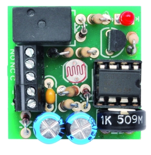
A lot of twilight switches are available on the market, what to invent then? This time we tried to act on size and we propose a project that, despite being a classic, adapts to one of the needs of modern times: miniaturization. In fact, what we present is a magnificent twilight switch a with relay output to control in low voltage loads (to handle loads operating at 220 VAC just use an adequate capacity relay to control the exchange) whose printed circuit board, complete with all components, measures just 29x29x15 mm!
Diagram

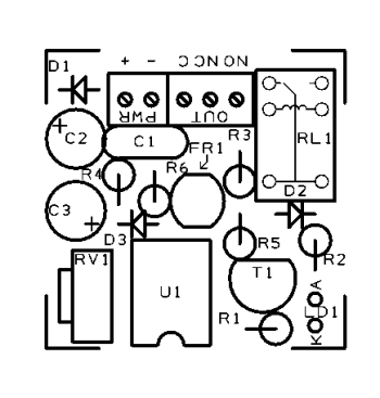
The diagram is very simple: an operational amplifier mounted as a comparator and a photoresistor we use to detect the level of lighting in the environment. To complete the circuit you’ll find also the actuator, which in our case is a small relay. As said, to detect the ambience illumination we use of a photoresistor dubbed FR1, which has maximum resistance in the dark (about 1 Mohm) and the minimum (some hundreds of ohms) at the exposure to a strong intensity light: this allows to detect the level of illumination of the environment on the basis of the value taken by the resistive component. To do this we insert a photoresistor in a voltage divider, doing so by referring to the voltage obtained at the output from the latter.
By using a divider we can use a comparator with a defined voltage threshold corresponding to a certain brightness value: in correspondence of the threshold the will be energized. The inclusion of a trimmer in the comparator network leaves us free to define the brightness level at which the relay must be activated.
Let’s see the operation in detail, assuming we start from a total darkness condition, with the FR1 resistance much higher than that of R3 and R5, and then the voltage present between the node formed by it with R3 and R6 being approximately equal to that which is detected downstream of the D1 diode and thus the same that feeds the U1.
If the cursor of the RV1 trimmer is far from the positive line (ie, the cathode of D1), the voltage present on the inverting input of the operational amplifier is lower than that localized on the non-inverting input. In this way, the U1 output goes to logic high and gets polarized basing on T1. T1 current collector conducts current and simultaneously feeds the relay coil and the R2/LD1 bipole, illuminating of the LED (thus signaling the activation of the twilight switch) and energizing RL1. RL1 switch closes between the C and NO, closing the circuit of the load connected to them.
When the light in the environment increases, the voltage brought from R6 and D3 to pin 5 of the U1 begins to lower, due to the fact that the resistance of the photoresistor starts to fall progressively, in relation with the intensity of the light that hits the sensitive surface. At some point in this process, the non-inverting input is at a lower potential than that brought on the inverting one from the RV1 trimmer and the comparator inverts the state of its output, which switches to low level and leaves the transistor T1 inhibited.
Now, the LED turns off and the movable load of the relay falls. If the brightness of the environment drops back, pin 7 of the U1 gets back to high and the relay is energized again (also the LED turns back).
The point at which the relay is energized and the LED lights up is regulated by RV1 trimmer. By bringing the cursor of this component to ground reduces you reduce the voltage at which the comparator returns to rest: plenty of light it is required to deactivate the relay. On the contrary, moving towards the D1 diode cathode, the voltage that pin 5 must reach grows and to trigger the relay you must submit to the photoresistor higher resistance values (and therefore a darker ambience).
Looking at the comparator circuit you can notice that the D3 serves to bring R6 potential to the operational, avoiding that C3 to discharge through it. D3 is inserted to achieve, together with the C3 capacitor, a kind of anti-commuting network indispensable to avoid the comparator to switch at the occurrence of a very short light variation (due for example to overflight of a bird or the movement of a person or a car). Both in the transition from dark to light and vice versa, the relay will start to ring because the comparator switches repeatedly since the resistance value taken from the photoresistor oscillates in the neighborhood of the one which determines the switching. The latter situation could also be avoided by retroacting U1 in positive, thus realizing a circuit hysteresis (with two different switching thresholds): in this case we opted for the normal comparator, filtering the voltage supplied by the divider that comprises the photoresistor by means of a RC network.
Having said that we should only look at the power supply circuit, consisting of the D1 diode (which protects the input terminals from reverse polarity) is located downstream of the power supply and the C1 and C2 capacitors (the purpose of which is to filter the power supply, especially if taken from a power line.
The circuit requires DC voltage to work, better if stabilized (otherwise the comparator may oscillate in the vicinity of the threshold voltage, despite the network RC filter), at values between 9 and 12 volt. The required current is of the order of 40 milliamps, thanks also to the adoption of a sub-miniature relay whose coil absorbs very little (about 15 mA).
A final detail concerns the D2 diode antiparallelly placed respect to the RL1 coil and therefore interdicted in normal conditions; this component is used when the transistor, by interdicting, interrupts the current in the coil of the relay while, due to the inductive nature of the inductances, the same reacts by generating an reverse extravoltage. This tension, if not suppressed by the fact that the diode, inversely polarized, short circuits it, would damage the collector junction of T1.
BOM
R1: 15 kohm
R2: 1 kohm
R3: 15 kohm
R4: 3,3 kohm
R5: 150 ohm
R6: 3,3 kohm
RV1: Trimmer 1 kohm MV
FR1: photoresistor 2-20k
C1: 100 µF 25VL
C2: 100 nF
C3: 100 µF 25VL
D1: 1N4148
D2: 1N4148
D3: 1N4148
LD1: LED 3 mm red
T1: BC547
U1: LM358
RL1: Relé 12V

Related Posts


3 Comments
Leave a Reply
-
 Arduino ISP (In System Programming) and stand-alone circuits
We use an Arduino to program other ATmega without...
- Posted 12 years ago
-

-

-
 GSM GPS shield for Arduino
Shield for Arduino designed and based on the module...
- Posted 12 years ago
-
 Small Breakout for SIM900 GSM Module
Some post ago we presented a PCB to mount...
- Posted 13 years ago
-
 Building a 3D Digital Clock with Arduino
Project to create a digital clock consisting...
- Posted 3 months ago
-
 Acoustic amplifier – in DIY Kit
This kit creates a microphone amplifier with an output...
- Posted 4 months ago
-
 Creating a controller for Minecraft with realistic body movements using Arduino
Project of a controller that maps body movements...
- Posted 4 months ago
-

-
 Holographic Christmas Tree
Beautiful project to create a Persistence of Vision...
- Posted 5 months ago
Pingback: APR-3 Rev.Preventing Relay - Any Electronics Co.,Ltd - Anyabb