- Building a 3D Digital Clock with ArduinoPosted 3 months ago
- Creating a controller for Minecraft with realistic body movements using ArduinoPosted 4 months ago
- Snowflake with ArduinoPosted 4 months ago
- Holographic Christmas TreePosted 5 months ago
- Segstick: Build Your Own Self-Balancing Vehicle in Just 2 Days with ArduinoPosted 5 months ago
- ZSWatch: An Open-Source Smartwatch Project Based on the Zephyr Operating SystemPosted 6 months ago
- What is IoT and which devices to usePosted 6 months ago
- Maker Faire Rome Unveils Thrilling “Padel Smash Future” Pavilion for Sports EnthusiastsPosted 7 months ago
- Make your curtains smartPosted 7 months ago
- Configuring an ESP8266 for Battery PowerPosted 7 months ago
A Comprehensive Comparison of Linux Development Boards
Today we present an overview of today’s market offering regarding ARM RISC microcomputer able to run a GNU/Linux distribution. And once again, this is just the beginning.
While the growth of such a device segment was predictable, it wasn’t easy to predict such an explosion. In fact we now have an heterogeneous set of options, with different characteristics, requiring a different approaches to for the optimization of the GNU / Linux operating system. In this post we’ll try to present, on the one hand, the unifying elements of different devices and, secondly, to classify each device based on its best use cases.
Let’s begin to point out a first list of devices to analyze, new ones appear every day but we’ll deal with them later.
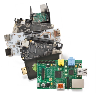 The ones we feature on this post are the following:
-
RaspberryPi
-
PcDuino
-
BeagleboneBlack
-
CubieBoard
-
MK802III
-
MK802IIIS
-
ODROID-U2
A first great classification can be done by taking into account the board processors or, better, the SoC (System On a Chip) that the device features. These are layered systems made of a CPU, a GPU and one or more RAM memory modules. Porting GNU / Linux from Intel x86 processors to these SoCs is a challenging task.
In fact, while manufacturers try to maintain standard features when developing Intel x86 processors mother boards, this standardization approach is not pursued by SoC assemblers, which tend to optimize the SoC “recipe” for the device they are intended to produce. Since GNU / Linux kernel, must be adapted to the hardware features of the device that houses it, it’s then clear that the so-called porting process should be run and customized for each type of SoC, an activity that complicates life enough to the development community.
Along with this essential diversity we also have different ways of managing I/O and communication peripherals that are made available. In fact a second classification criterion can be that of the presence or absence of GPIO and communication devices on dedicated connectors.
A third type of classification comes from the different boot processes, which also involves different procedures for installing GNU / Linux.
According to the mentioned characteristics we can try to determine the ideal use case of the different devices: teaching, embedded development, networking or office work.
But let’s go back to our own devices.
RaspBerryPi still is one of the best boards to start from, especially since the boot process starts immediately from the SDCard, and it is almost impossible to create damages with the software: in case of awkward operations you can just reload the operating system image from the SDCard and it’s done. From the hardware point of view the GPIO is a bit ‘more delicate and it cannot stand voltages above 3.3 V.
The bulk of the group of devices that we consider is “driven” by the Allwinner A10 SoC, based on ARM Cortex A8. In this group you have the PcDuino and CubieBoard.
The Beaglebone Black sports a Texas Instruments Sitara XAM3359AZCZ100 SoC, while MK802III and MK802IIIS and are built around the SoC, Rockchip RK3066 which includes the dual core CPU ARM Cortex A9.
PcDuino, Beaglebone Black and CubieBoard, as the eRaspberry Pi, have expansion connectors equipped with GPIO and other devices that we’ll describe.
We can anticipate that the GPIO management is different for almost each of the devices, making them more or less suitable for unexperienced users.
MK802III and MK802IIIS are in the USB “Stick” format, the first appearance of multicore systems in lilliputian size and price.
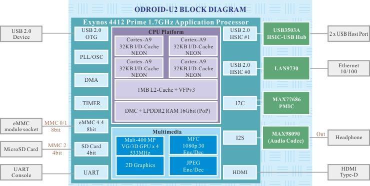
Finally we have the ODROID-U2 a sort of monster, sized 5x5x5cm, with a Samsung Prime Exynos4412 SoC that includes a ARM Cortex A9 quadricore CPU, a cutting-edge systems that could compete with traditional PCs that we use every day.
This comparison table shows both the technical information of the devices and our impressions in terms of ease of installation of GNU / Linux and suggested use cases:
|
RaspberryPi |
PcDuino |
BeagleBone Black |
CubieBoard |
MK802III |
MK802IIIS |
Odroid-U2 |
|
|
SoC |
Broadcom BCM2835 |
Allwinner A10 |
Sitara XAM3359AZCZ100 (Texas Instruments) |
AllWinner A10 1 GhZ |
CPU RK3066 Dual Core – Cortex-A9 1.6GHz |
CPU RK3066 Dual Core – Cortex-A9 1.6GHz |
Samsung Exynos4412 Prime 1MB L2 cache |
|
CPU |
700 MHz ARM1176JZF-S |
ARM Cortex A8 1GHz |
ARM Cortex A8 1GHz |
ARM Cortex-A8 coprocessors |
Cortex-A9 dual core |
Cortex-A9 dual core |
Cortex-A9 quad Core |
|
GPU or graphics processor |
Broadcom VideoCore IV, |
OpenGL ES2.0, OpenVG 1.1 Mali 400 core |
SGX530 3D, 20M Polygon/S |
Quad- Core 2D/ 3D/ OpenGL ES2.0(AMD Z430)/ OpenVG1 |
Quad-Core 2D/ 3D/ OpenGL ES2.0(AMD Z430)/ OpenVG1.1 |
3D accelerator Mali-400 Quad Core 440MHz |
|
|
RAM |
512MB (mod. A, rev. 2) |
1GB |
512 MB |
1GB |
1GB |
1GB |
2GB LP-DDR2 |
|
RAM (data) |
2GB Flash |
2GB embedded MMC |
NAND (max 64GB) SATA II, SD Card 3.0 |
8GB Flash |
8GB Flash |
||
|
Video |
HDMI Composite video |
HDMI |
HDMI |
HDNI VGA, TV e Webcam via GPIO |
HDMI |
HDMI |
1080p HDMI |
|
Audio |
HDMI Jack OUT |
HDMI |
HDMI |
HDMI Jack IN Jack OUT |
HDMI |
HDMI |
Standard 3.5mm headphone jack |
|
USB |
2 |
2 |
2/3 |
Ports HDMI(male),Micro SD slot, USB host (full sizeUSB), USB power port(micro USB); LED(Blue) |
Micro SD slot, USB host*1,USB OTG*1, USB power port; LED(Blue) |
||
|
Network |
10/100Mbps RJ45 |
10/100Mbps RJ45 |
Ethernet 10/100, RJ45 |
Ethernet 10/100 |
WiFi 802.11 b/g/n Realtek RTL8188EUS |
Mediatek MT5931 (Bluetooth v2.1: Mediatek MT6622) |
Ethernet 10/100 |
|
GPIO |
8 GPIO pin, I²C, SPI, UART |
Compatible with Arduino |
Two 46 pin configurable bus including: McASP0, SPI1, I2C, GPIO(65), LCD, GPMC, MMC1, MMC2, 7 |
Two 48 pin configurable bus including: I/O digitali 2c (twi) spi rgb/lvds csi/ts fm-in adc cvbs vga spdif-out touch-panel |
NO |
NO |
NO |
|
Data |
SD Card |
microSD |
microSD |
MicroSD Porta SATA per Hard disk |
microSD fino 32 GB |
microSD fino 32 GB |
MicroSD Card Slot |
|
Power |
5v, 1a |
5V, 700mA |
5V, 700mA |
5V 2A |
5V |
5V |
5V, 2A |
|
Size |
85,60 mm × 53,98 mm |
125x52mm |
3.4” x 2.1” 6 layers |
10×6 cm |
(mm) 90mm*40mm*13mm |
(mm) 90mm*40mm*13mm |
5x5x5 cm |
|
Predefined Software |
GNU/Linux |
GNU/Linux Angstrom |
Android |
Android 4.1 |
Android 4.1 |
Nessuno |
|
|
Supported OSes |
Raspbian, |
Linux3.0 + Ubuntu 12.04 Android ICS 4.0 |
Angstrom Debian Ubuntu Fedora ArchLinux Gentoo Sabayon |
Supports different GNU/Linux distros Allows multi OS installations via BerryBoot |
Picuntu |
Picuntu |
Ubuntu (customized) |
|
Isntallation |
SD Card BerryBoot |
Predefinito |
Predefinito |
BerryBoot Immagine SDCard |
tool PicuntuKernelInstaller |
tool PicuntuKernelInstaller |
Immagine SDCard |
|
Use Cases |
Learning Embedded apps Robotics |
Basic Learning Embedded apps |
Basic Learning Embedded apps Robotics |
Advanced Learning Embedded apps Video Robotics |
Stand alone Networking Video |
Stand alone Networking Vide |
Desktop PCs Servers Graphics Video Imaging |
|
Ease of Use |
Easy |
Easy |
Easy (but closed) |
I/O and peripherals are not so easy to manage |
Complex |
Complex |
Easy |
RaspberryPi
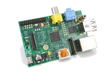 The RaspberryPi board is a true single board computers the size of a cracker. It’s been developed in the UK by RaspberryPi Foundation with the aim of achieving a low-cost computing platform to stimulate the teaching of computer science in schools, especially in developing countries.
The heart of the computer is a Broadcom BCM2835 SoC that includes a 700 MHz ARM1176JZF-S processor, a VideoCore IV GPU, a DSP processor and 512 Mb of RAM.
No hard disks or solid state are required as the operating system and the mass memory are located in the SD Card which is also the only boot device.
Let’s see how is the GPIO configured to connect the board with external hardware.
From the physical standpoint you have a 2,54 mm pitch connector in two rows of 13 pins each.
On this connector you have the 3.3 V power on pin P1-01, 5V on pin P1-02, ground on pin P1-06 and then 17 more pins for input/output, which can be reconfigured for additional functions such as I2C, SPI, UART, Serial and others.
Remember that the I/O pins work with 0 and 3.3 V and DO NOT tolerate 5V; also there is not a surge protector. In substance, the GPIO pins are connected directly to the pins of the processor. All this leads users to design interface boards with buffer, conversion levels, analog I/O and protection devices, in order to avoid the risk of damaging the RaspberryPi .
Remember that each pin is marked with a number that identifies its position on the connector (P1-01 to P1-26) and one or more names that specify the or functions. For example, the pin P1-07, is identified with the name GPIO4. However the connector pins can be reconfigured in order to access many of the signals of the processor.
PCDuino
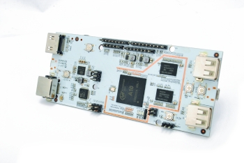 PcDuino is a mini PC development board based on Alllwinner A10 SoC, with CPU ARM Cortex A8 1 GHz. The board comes already installed with a distribution of GNU / Linux of the Debian family, which actually allow you to reuse much of the RaspberryPi experiences. You can also install, a version of Android ICS, or upgrade to new GNU / Linux versions as they are released. From the end user perspective, it is a nice convenience, allowing you to immediately start to experiment with a bunch of applications already available with appreciable performances.
Besides the card, the package contains a power supply that operates on 220V. There is also an HDMI cable and a USB hub with a USB cable.
The board features:
-
Two USB Host ports,
-
RJ45 Ethernet port,
-
the power connector,
-
a serial connector for the console debug
-
the accommodation for Micro SDCard,
-
A small “reset” button
-
GPIO connectors that we’ll describe below
Let’s focus on the main feature of this card, which is a GPIO connectors structure that reflects the size and connections of those on the Arduino Uno.
On the connectors, reflecting the type but not the arrangement of those on the Arduino Uno are available the same I/O terminals, and in particular:
-
Up to 13 digital I/O pins, many of which of course can be configured to provide other types of interfaces;
-
Up to 6 Analog/Digital inputs pin, two of which (ADC0 and ADC1) have a resolution of 6 bits, while the others have a 12-bit resolution ,
-
two hardware PWM outputs, (PWM1 and PWM2) that can generate frequencies up to 24Mhz: the other PWNs are simulated by the GPIO and can support frequencies up to 100 Hz, not very accurate;
-
I2C interface,
-
SPI interface.
An important note: the levels of the GPIO pins and communication buses are of 3.3 V, therefore it is important to take this into account, especially in the case of using a compatible Arduino shield. Furthermore, and more importantly, the reference voltage for the analog digital conversion pin: the ADC0 and ADC1 pins, use an internal reference voltage of 2 V, while the other pins use the reference voltage of 3.3 V.
With regards to the use of the board, we already anticipated that this is more or less equivalent to using the operating system of the RaspberryPi, commands, and adding packages included.
BeagleBone Black
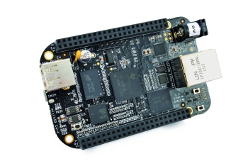 Black BeagleBone, also adopts an ARM Cortex A8 1 GHz CPU but within a SoC from Texas Instruments called Sitara AM335x. The Black BeagleBone board has 2GB of on-board storage memory and it comes pre-installed with the Ångström GNU / Linux distribution. The slot for the micro SD Card can be used to increase the mass memory available or to install an alternative operating system. RAM is 512 MB DDR3L. There are two USB ports (one is also USB host), a connector for serial debugging, Ethernet, HDMI video output, the power outlet and the power button. The two sockets, each sporting 44-pins with a 2.54 mm pitch, provide:
-
65 digital inputs / outputs;
-
7 analog inputs,
-
4 serial ports,
-
2 SPI buses
-
2 I2C buses
-
8 PWM outputs,
-
4 Timers,
and more as we discover.
When switched on, the system will boot in seconds providing the opening screen (see figure). It provides a number of applications from scratch such as LibreOffice, Gimp, and administration tools (see figures).
The approach adopted by the creators of the BeagleBone is to make it a learning tool. In fact, when you first start you already have an internal website, which contains the board’s documentation and the development environment Cloud9, also based on a web interface, which provides the development language, Bonescript, a development language that mirrors the logic of Arduino, whose documentation is available on the internal web site.
Cubieboard
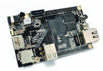 First of all compliments: the Cubieboard is, at least in my opinion, pretty much the maximum you can get from the boards that use a 32-bit RISC ARM processor. It could be your office workstation. Among the features that impress there’s the presence of a SATA connector to connecting a hard disk. Also it sports an audio jack for both audio output and input. Finally two buses are available, terminated on two connectors, each with two rows of 48 pins at 2mm pitch, for a total of 96 pins, which connect the ports of the processor to the outside of the board.
The packaging adequately protects the board and includes a power cable consisting of USB power cable of A type with an output jack suitable for the socket on the board.
On the board you can see the Ethernet and USB connectors, the two audio jacks (input and output), the micro SDCard connector (up to 64 GB). On the top of the figure you can see the SATA connector that can withstand a 2.5-inch disk (if you use larger size disks you need to feed them externally). Finally, a little curiosity, in the upper left we see an infrared sensor. This type of sensor was very common in laptops and vintage mobile phones, then they disappeared. In this case, however, the idea is not so farfetched as it might appear at first glance, as it allows us to use a built in infrared remote control applications to be integrated into home automation and such.
The board comes with the Android operating system pre-installed (in the NAND memory partition). If there is an SD card with a valid boot partition the operating system it’s loaded and launched, otherwise it goes with Android. There are two ways to load an operating system on the external Cubieboard card. The first is to build a SD Card from the image of an operating system.You can download the most recent and reliable from:
http://dl.cubieboard.org/software/ubuntu/
Is a Linaro distribution, a light version of Ubuntu, which in turn is a derivative of Debian. This system already contains support for GPIO.
The ports of the processor can be assigned to the pins of the connectors through a slightly complicated process, a small price to pay that allows great flexibility. This characteristic makes it less useful for learning respect to RaspberryPi or PcDuino, but if you want to build advanced applications, it is worthwhile to face the steeper learning curve.
The problem with this configuration complexity with the GPIO is due to the fact that Allwinner, the producer of the A10 SoC, is not particularly interested in supporting GPIO featured in ARMv CPUs, because their main market is represented by tablets and smartphones manufacturers.
Cubieboard designe, Tom Cubie, developed the SUN4I-GPIO driver that is not as flexible as the the RaspberryPi one and does not allow you to manage GPIO pins just as easily.
With the SUN4I-GPIO driver you need to permanently configure each pin you want to use as input or output in a script.bin file, located on your boot partition. To change the pin configuration you must disable the driver, transform the script.bin file format in a “readable” script.fex, make the changes, recompile the script.bin file and reload the driver.
Nevertheless, in our opinion , it is still worthwhile. We just want to give you a taste of the process to be followed for the configuration and use of digital I/O pins.
First, in Figure XXX. You can see the mapping of the GPIO pins of the two connectors available on the board. The names (PE, PD, PG, etc.. ) followed by a number refers to the pins of the A10 SoC I/O ports, and are described in the datasheet of the same chip.
MK802III and MK802IIIS
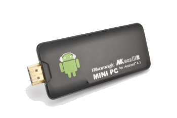 The new MK802 versions, the III and IIIS, recently replaced the old ones. The performance increase of these versions is more than remarkable. In fact, we are overcoming another line, the one that divides the single processor devices from the multi processors. The Rockchip RK3066 SoC houses ARM Cortex A9 operating up to 1.6 GHz
The modules are natively equipped with Android 4.1 and, as far as GNU / Linux is concerned, a distribution of Picuntu (always of the Ubuntu family) now stable, is available but it forces us to deal with the problems due to SoC diversity and a fairly complex boot process.
The MK802III SoC differs from that used on the MK802IIIS for what concerns wireless connectivity. The MK802III only sports WiFi connectivity using the Realtek RTL8188EUS, while MK802IIIS has both WiFi and Bluetooth, using respectively Mediatek MT5931 and MT6622. The Picuntu version available at the moment of writing this post (RC3), only has drivers for the RTL8188EUS chip of MK802III, which works fine in WiFi, while for MK802IIIS, for now you need to use an external dongle.
Instead, it works perfectly the Ethernet connection using an Ethernet USB Converter such as the with the MK802(II).
Let’s quickly see the installation process of Picuntu, valid for both the devices.
In this case it is not enough to create an image on the SD card and insert it into the MK803III slot since the device is not designed to boot directly from SD Card. MK802III uses the internal flash memory, appropriately divided so as to contain the boot partitions, the kernel and a recovery partition. The recovery partition is used to gain access, with a special procedure, to the device if the primary operating system is ruined. To use GNU / Linux you just use the recovery partition where you install the Picuntu kernel. Then you turn on your device, you leave Android to start and then you reboots forcing it to use the recovery partition.
To do this you’ll need to enable the SuperUser(root), which in turn requires an appropriate procedure.
Odroid-U2
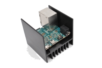 What we face here is a 5 cm side “cube”, with most of the space due to the heatsink. Inside you’ve a square printed circuit board with a Samsung Exynos4412 SoC with a 4 processors CPU running at 1.7 GHz, plus 2 GB of RAM, and a Mali400 video processor.
This SoC was originally designed for high-end mobile phones, then a special attention was paid to size and consumption. With a consumption of less than 5 W it offers a pretty impressive power/consumption ratio. Few doubts stand on the future success of the ARM RISC technology. For the rest, we are facing a real miniature PC. We have an Ethernet jack, two USB ports, a micro HDMI and the power connector. Unfortunately we do not have a SATA socket for an harddrive and not even a USB 3 port. The Exynos4 SoC does not include them, while the Exynos5 Soc provides a SATA connector, but sports a two processors CPU.
Hopefully the success of these devices will lead manufacturers to converge towards a bit ‘more consistent configurations, in order to facilitate the life of operating systems developers, which currently are literally going crazy to follow all the specificities of individual products. This device is is not only for electronics experts, but it is a monster, and from a certain point of view, it has great ease of use. Compared to a traditional PC, which requires the installation and configuration of an operating system and applications, you just download the optimized Ubuntu distro from http://dn.odroid.com/Ubuntu_U2/20130503/xubuntu- 04.13-desktop-armhf_odroidu2_20130503.img.xz , then you unzip the file and transferred the image to a (preferably class 10) Micro SD Card of at least 8GB and you’re done.
Insert the SD card into the slot and give power, then load what you want to use. We installed Libre Office, Firefox, Geogebra (the simulation software of Geometry and Calculus). Then we opened a multitude of windows. It worked without any problem.
Conclusions
After reviewing all the boards described we tried to find the common thread of the evolution of these devices, without wanting to say a board is better than others. Also you must take into account that the quality, versatility and ease of use of each board depends, in addition to the hardware recipe, on the maturity and completeness of the available operating systems. From this point of view the difference are still at different stages of evolution, due to the aforementioned difficulty of adapting a hardware that is still too loosely standardized. All this makes it very difficult to compare the boards. This class of products is still only in its infancy, but it’s certainty candidate to gain a relevant microcontroller market share.

Related Posts


9 Comments
Leave a Reply
-
 Arduino ISP (In System Programming) and stand-alone circuits
We use an Arduino to program other ATmega without...
- Posted 12 years ago
-

-

-
 GSM GPS shield for Arduino
Shield for Arduino designed and based on the module...
- Posted 12 years ago
-
 Small Breakout for SIM900 GSM Module
Some post ago we presented a PCB to mount...
- Posted 13 years ago
-
 Building a 3D Digital Clock with Arduino
Project to create a digital clock consisting...
- Posted 3 months ago
-
 Acoustic amplifier – in DIY Kit
This kit creates a microphone amplifier with an output...
- Posted 4 months ago
-
 Creating a controller for Minecraft with realistic body movements using Arduino
Project of a controller that maps body movements...
- Posted 4 months ago
-

-
 Holographic Christmas Tree
Beautiful project to create a Persistence of Vision...
- Posted 5 months ago
Pingback: A Comprehensive Comparison of Linux Development...
Pingback: A Comprehensive Comparison of Linux Development...
Pingback: A Comprehensive Comparison of Linux Development...
Pingback: A Comprehensive Comparison of Linux Development Boards
Pingback: Linux development boards « Labrigger
Pingback: A Comparison Of Different Input Devices For A 3d Environment – Dolove.info